Introduction to oil fume exhaust device:
The fans of the oil fume transmission and exhaust device are all horizontal structures, and there is a dynamic seal between the impeller shaft and the volute. Oil accumulates at the bottom of the volute, and the oil between the impeller shaft and the volute is tight. The fan is an ordinary centrifugal fan, which either has insufficient output or excessive negative pressure, resulting in oil water ingress, turbine oil emulsification, oil pipeline corrosion, and malfunctioning regulating components, posing a serious threat to the safe operation of the unit- It is not due to excessive negative pressure that a large amount of turbine oil is extracted, resulting in "oil spraying" at the discharge port, which wastes a lot and also affects the civilized production of the power plant; At the same time, due to excessive negative pressure, a large amount of shaft seal steam enters the bearing box and then returns to the main oil tank through the main oil pipe. During transportation, it condenses into water, causing the turbine oil to carry water and emulsify the oil, endangering the safe operation of the unit. On the other hand, the transmission fan is usually only installed on the main oil tank without considering the bearing box. The accumulation of oil fumes in the bearing box forms a positive pressure, causing the turbine oil to "bulge" out of the bearing box, polluting the site and posing a fire hazard.
Oil fume exhaust device -:
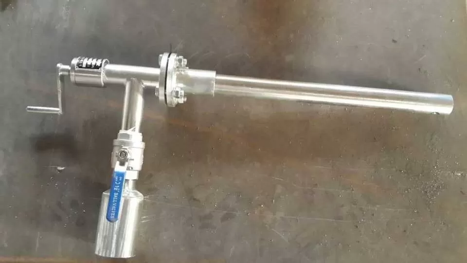
1. A complete set of oil fume exhaust device - sealed, vertical structure, - any leakage, - work forever;
2. Adjustable output, P-Q curve - smooth, ensuring that the main oil tank and bearing box operate under a slight negative pressure of around -300Pa;
3. The impeller and casing are made of different materials, which will not produce sparks and are safe and reliable;
4. Adopting a three oil fume separation device to separate oil fume, protecting the production environment and achieving civilized production;
5. Oil fume exhaust device - maintenance design, saving material consumption, reducing worker maintenance workload;
6. A high intelligent oil fume exhaust device equipped with variable frequency automatic control PID adjustment function, which automatically adjusts the fan speed to achieve the goal of automatically adjusting negative pressure;
7. Using cast impellers, dynamic balance - energy -, sturdy.
Design concept of oil fume exhaust device:
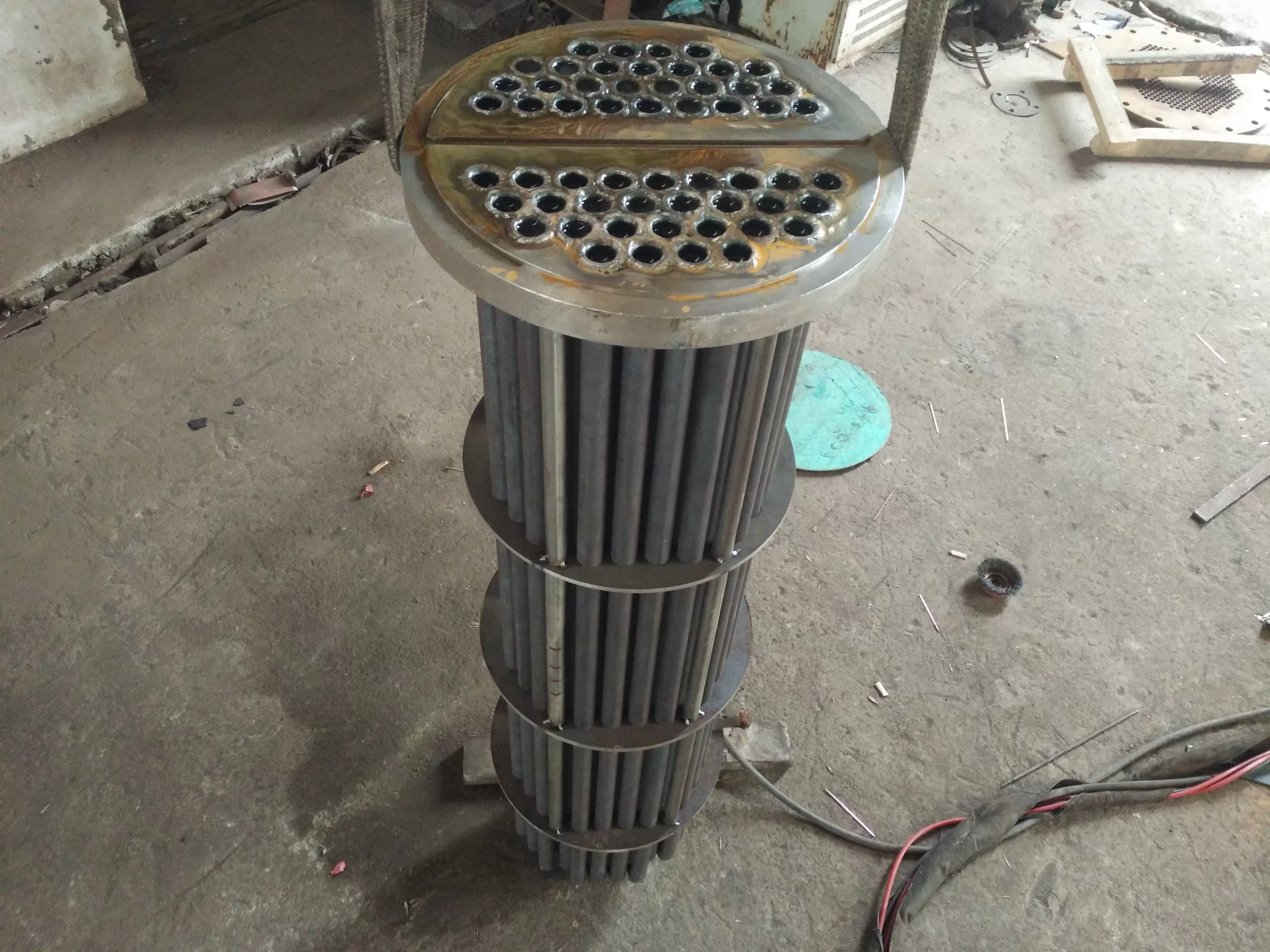
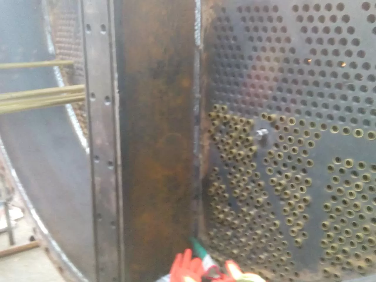
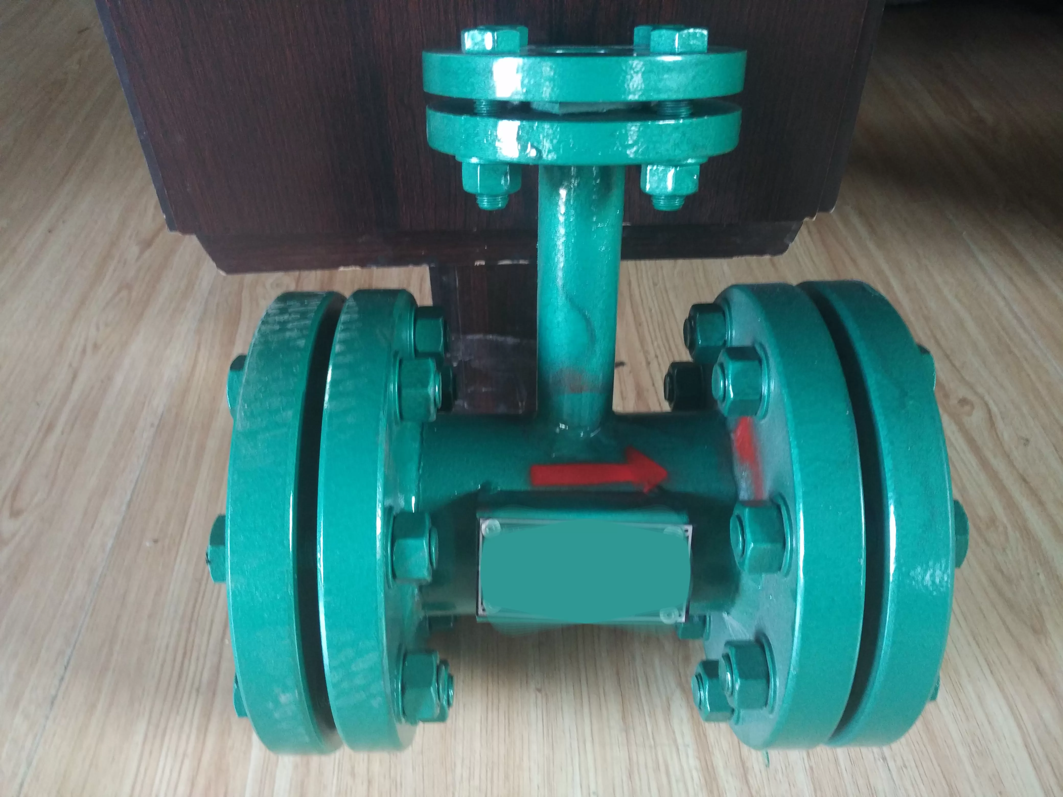
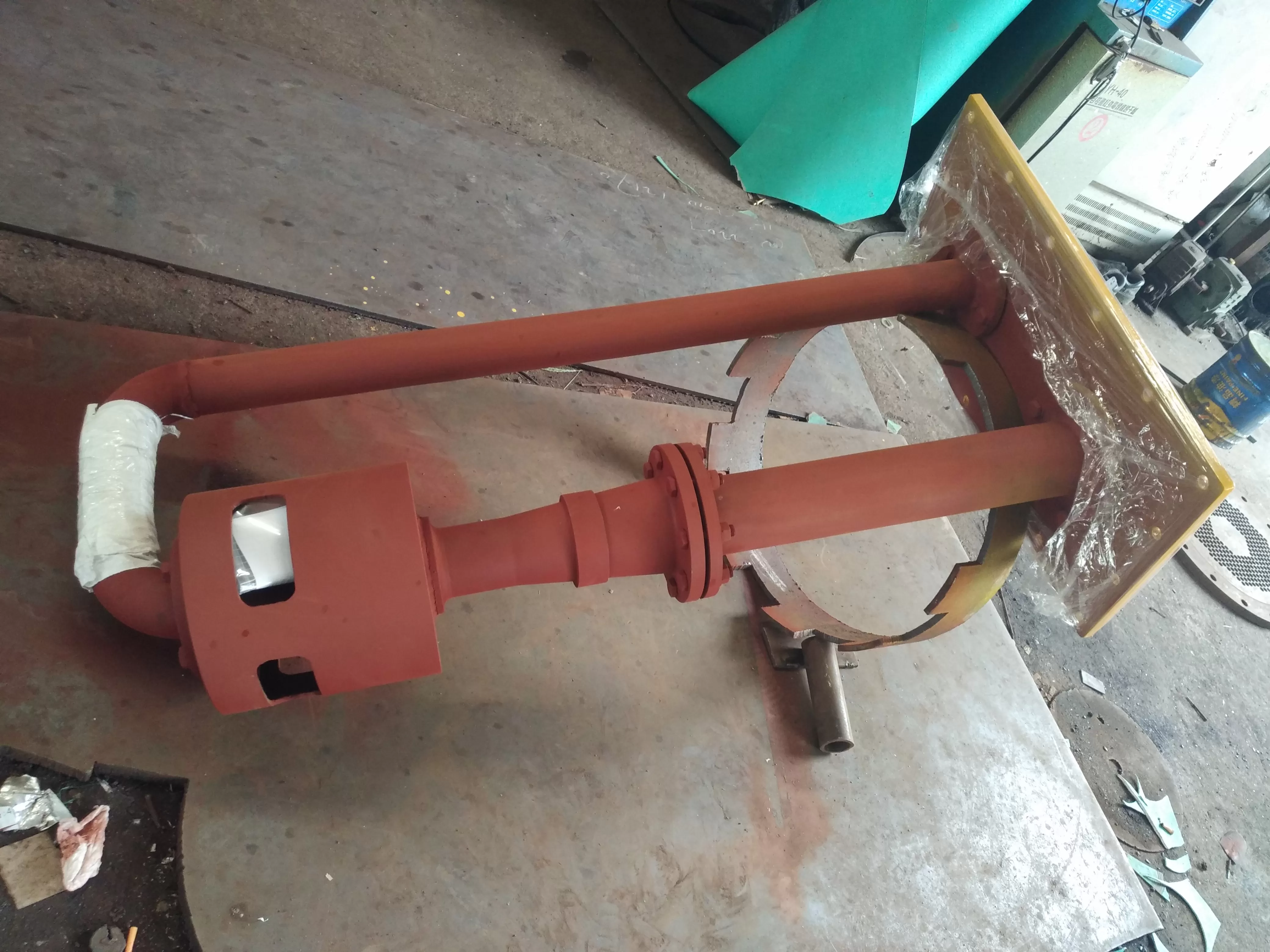
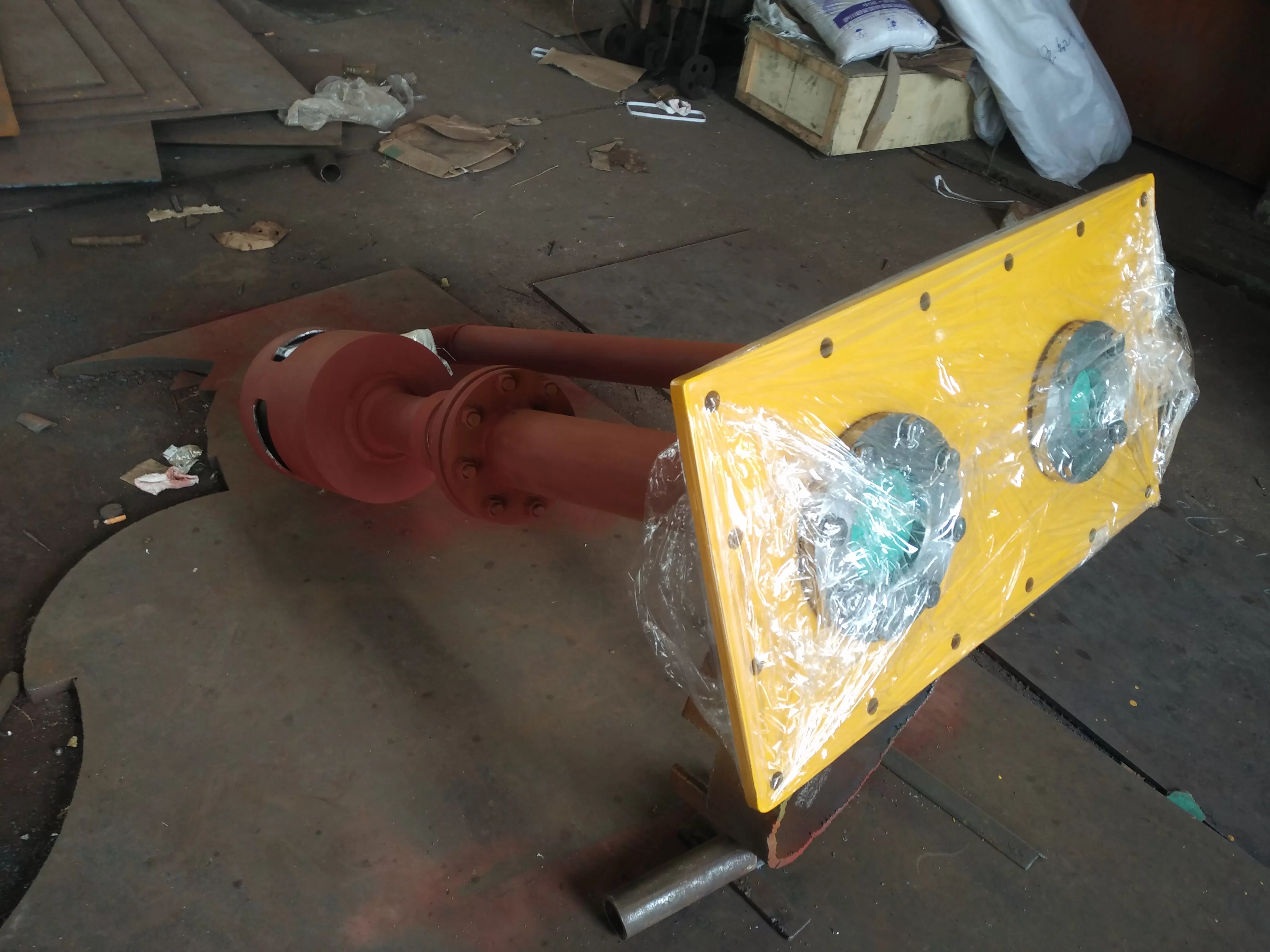
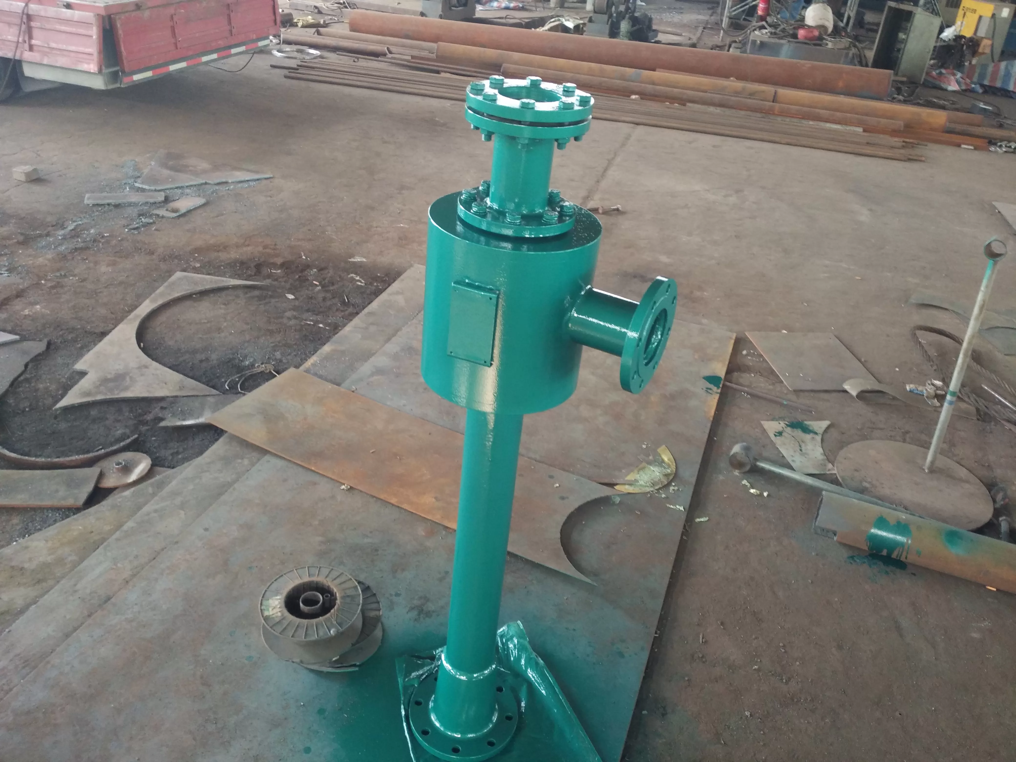
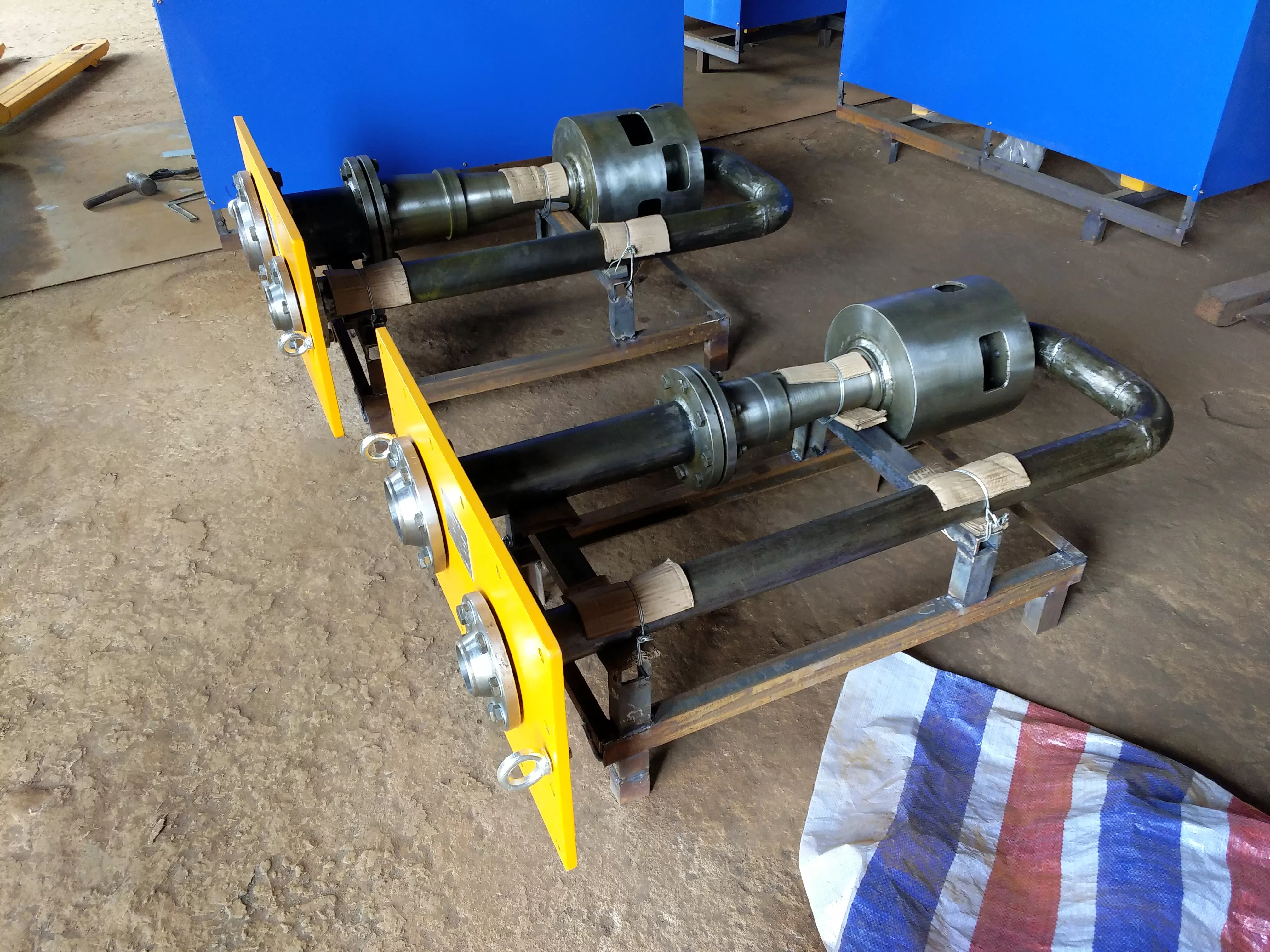
In response to the defect of the transmission fan, it has been changed from "horizontal" to "vertical", with an oil drainage circuit inside, and there will be no oil accumulation inside the volute; The motor is connected to the volute as a body, and the sealing between the impeller shaft and the volute is changed from dynamic sealing to static sealing, making it easy to seal; The filter type separator made of materials has replaced the old spiral structure, and the oil fume separation has been fundamentally improved, meeting the requirements of civilized production; In response to the drawback that the impeller and volute of the transmission fan are both made of steel and are prone to sparks, a lightweight aluminum alloy material is used to make the impeller, which avoids the generation of sparks and prolongs the use of bearings and motors.
Due to changes in the amount of oil smoke and steam generated by the unit during operation and time, the constant speed operation of the motor is unreasonable and will consume energy. Our company has developed a highly intelligent oil fume exhaust device with a variable frequency speed control system, which can monitor the negative pressure situation of the oil tank, operate in a closed loop, automatically adjust the fan speed, and maintain a micro negative pressure state of around -300Pa in the main oil tank and bearing box. It can also be designed according to the actual situation of the power plant, with corresponding DCS interfaces reserved.
In terms of installation, the original fan was only installed on the main oil tank without considering the bearing box, which is a defect. Because the return oil pipe is relatively long, the shaft seal steam gradually condenses into water after entering the bearing box, and the situation of oil water ingress is quite strict. So we are based on the renovation of the original fan in the main oil tank
Defects in the transmission fan of the oil fume exhaust device:
The transmission fans are all horizontal structures, and there is a dynamic seal between the impeller shaft and the volute. Oil accumulates at the bottom of the volute, and the oil between the impeller shaft and the volute is tight. The fan is an ordinary centrifugal fan, which either has insufficient output or excessive negative pressure, resulting in oil water ingress, turbine oil emulsification, oil pipeline corrosion, and malfunctioning regulating components, posing a serious threat to the safe operation of the unit- It is not due to excessive negative pressure that a large amount of turbine oil is extracted, resulting in "oil spraying" at the discharge port, which wastes a lot and also affects the civilized production of the power plant; At the same time, due to excessive negative pressure, a large amount of shaft seal steam enters the bearing box and then returns to the main oil tank through the main oil pipe. During transportation, it condenses into water, causing the turbine oil to carry water and emulsify the oil, endangering the safe operation of the unit. On the other hand, the transmission fan is usually only installed on the main oil tank without considering the bearing box. The accumulation of oil fumes in the bearing box forms a positive pressure, causing the turbine oil to "bulge" out of the bearing box, polluting the site and posing a fire hazard.
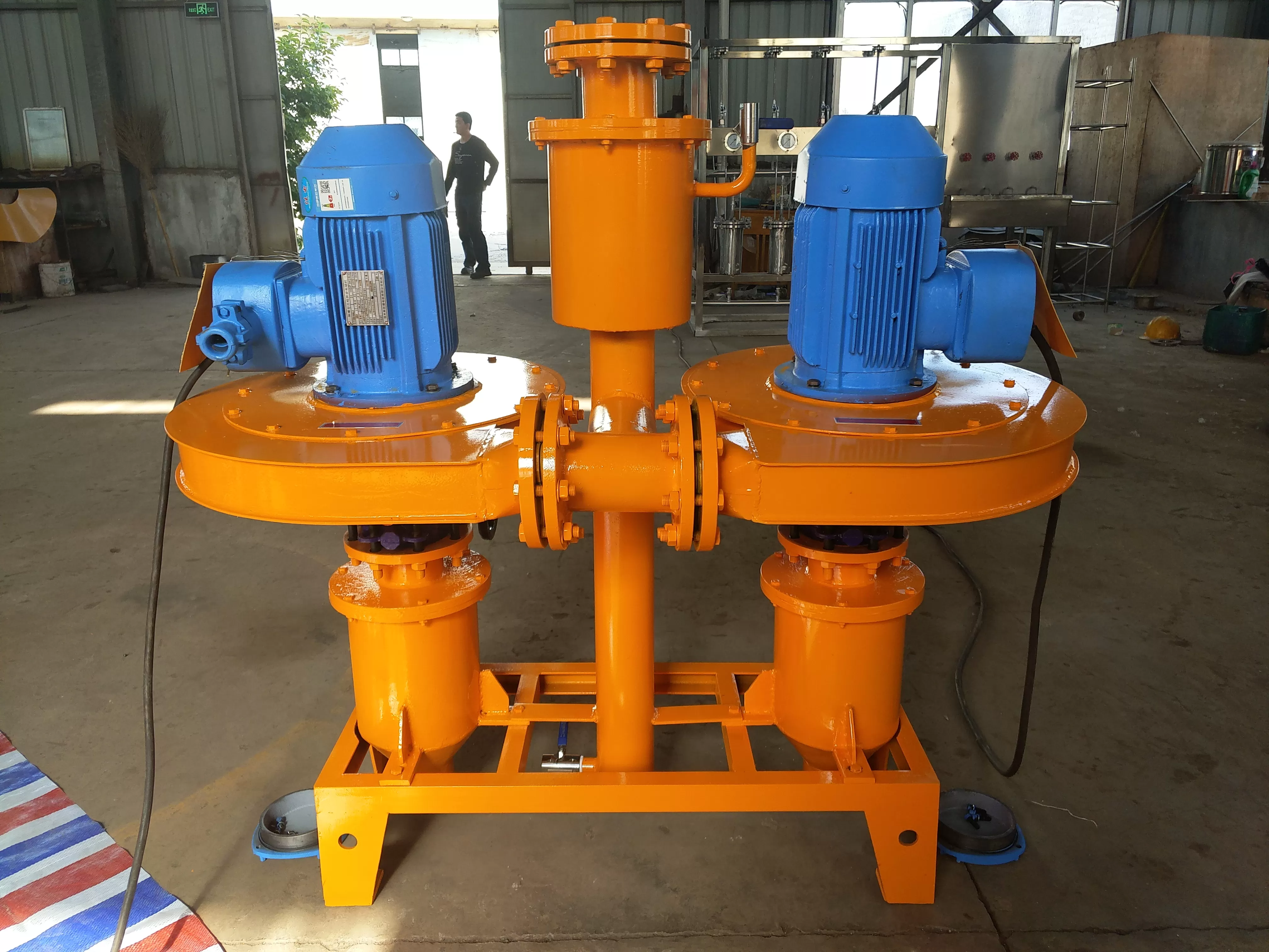
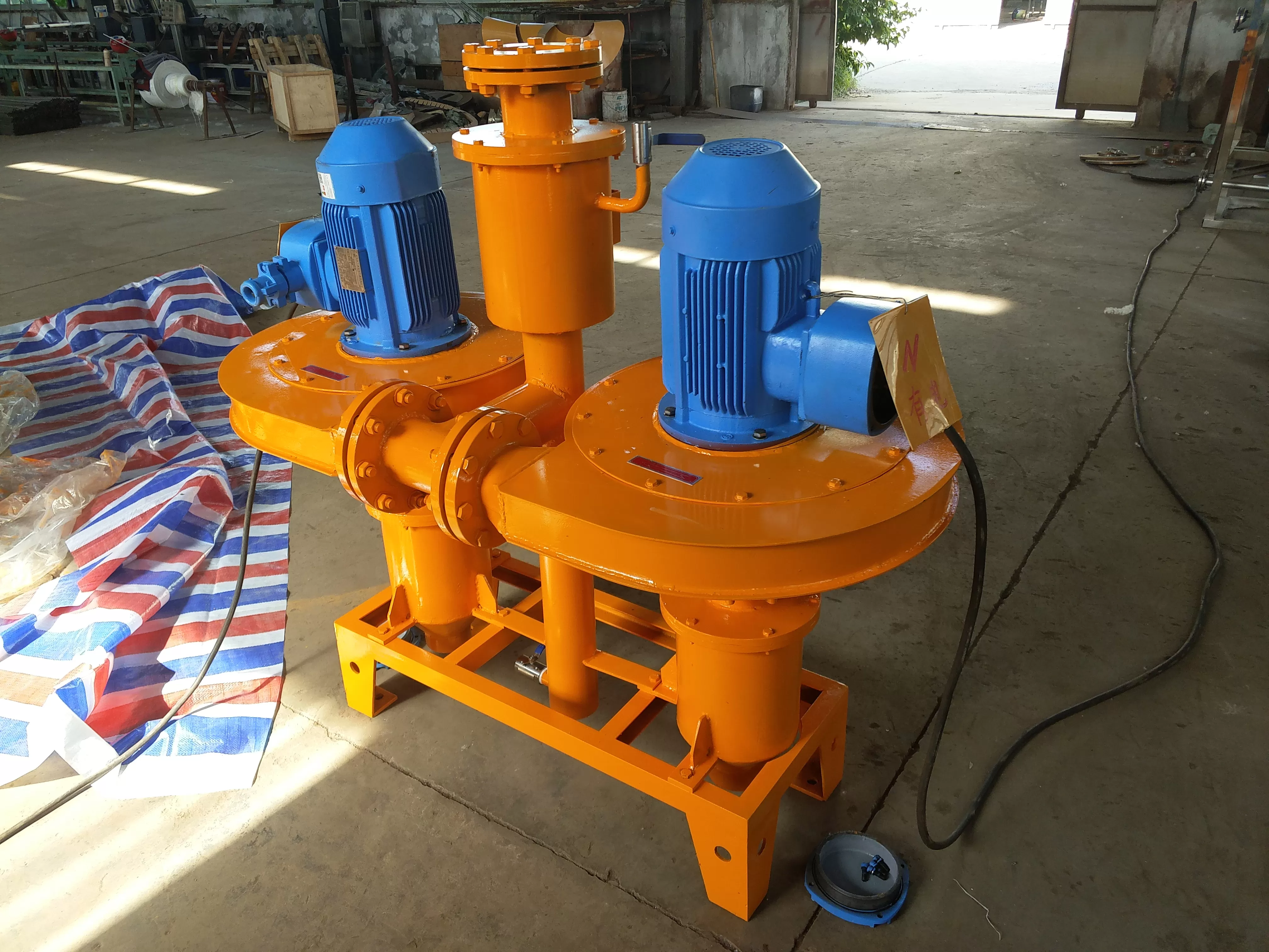
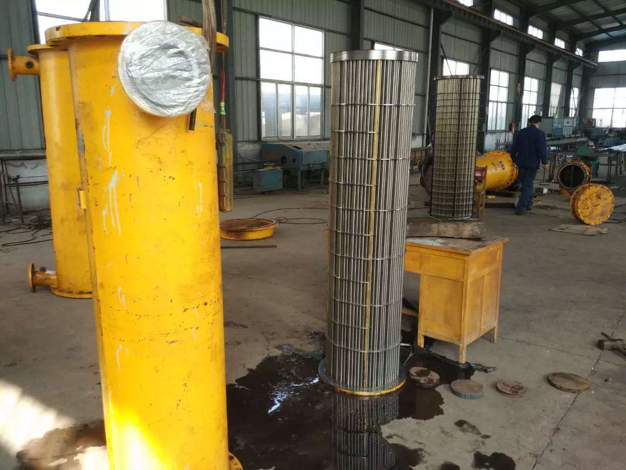
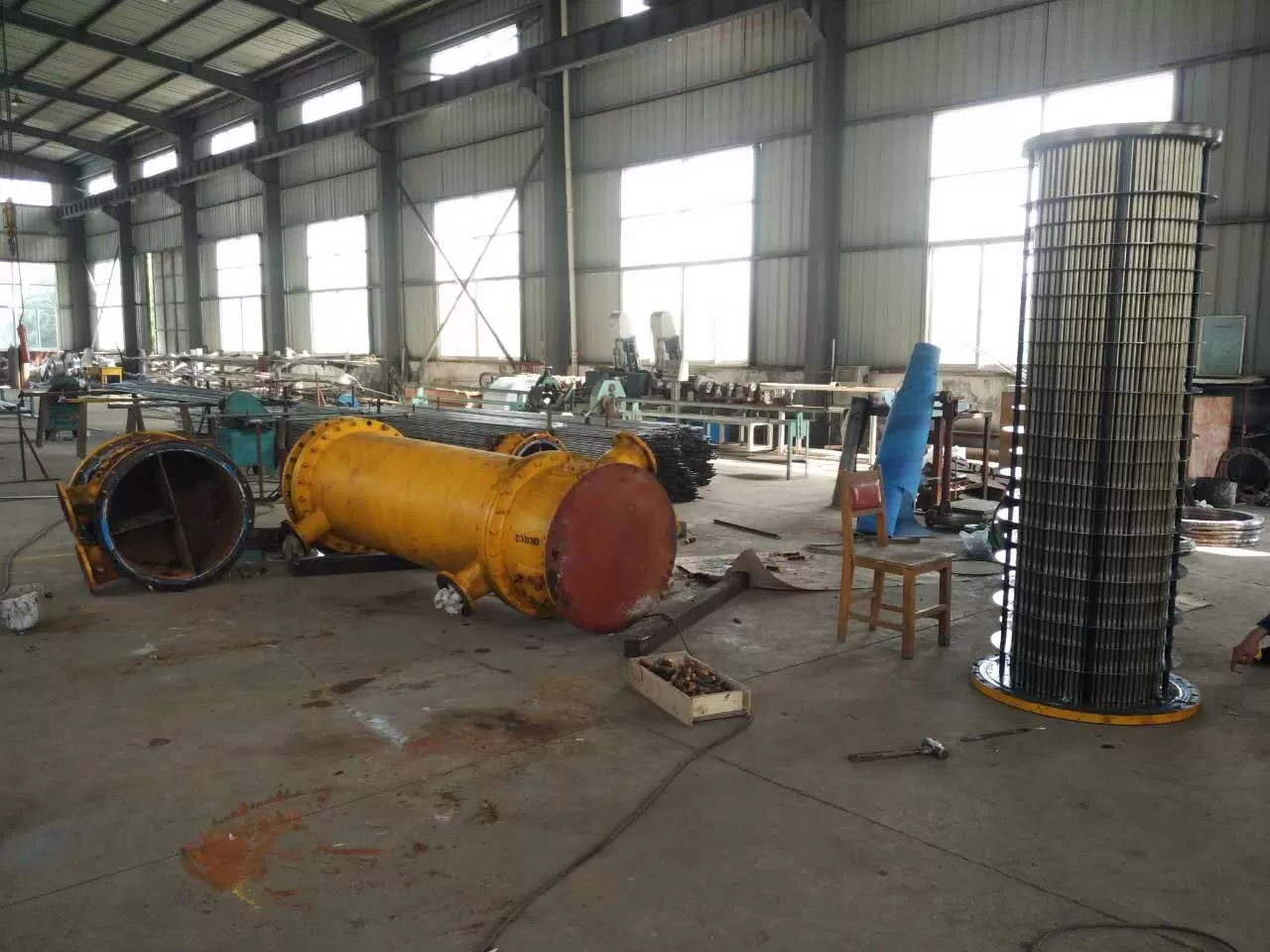
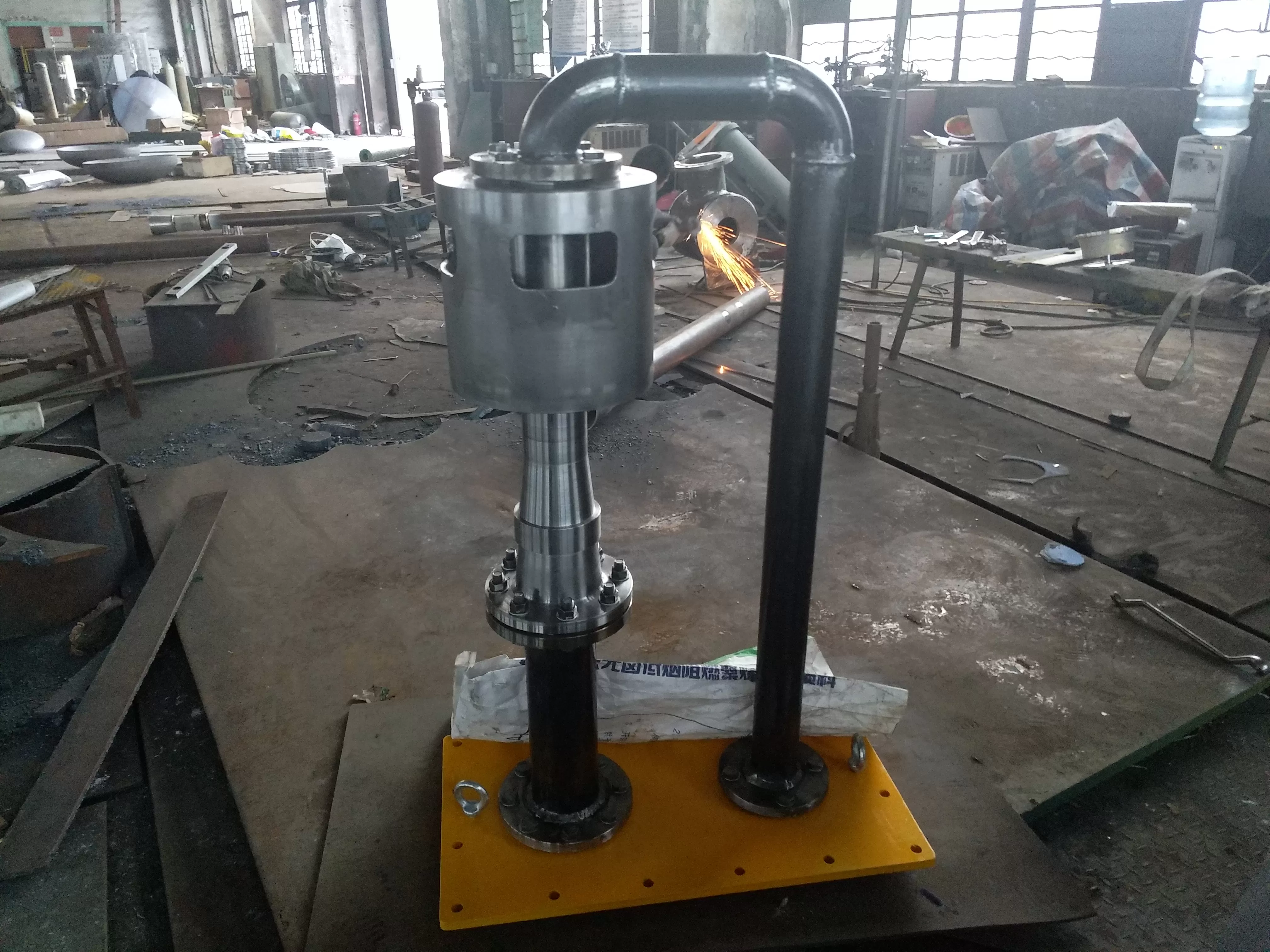
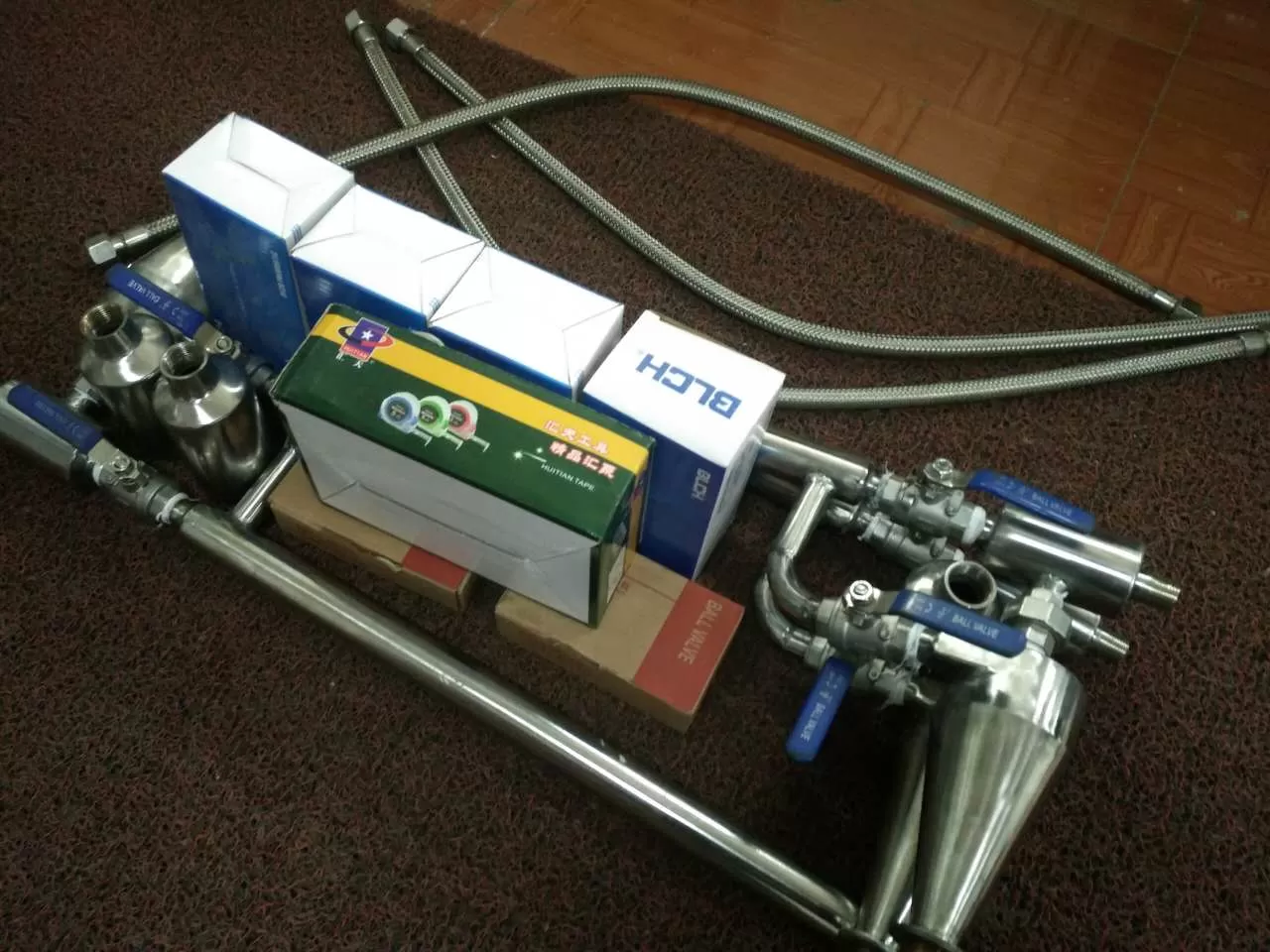
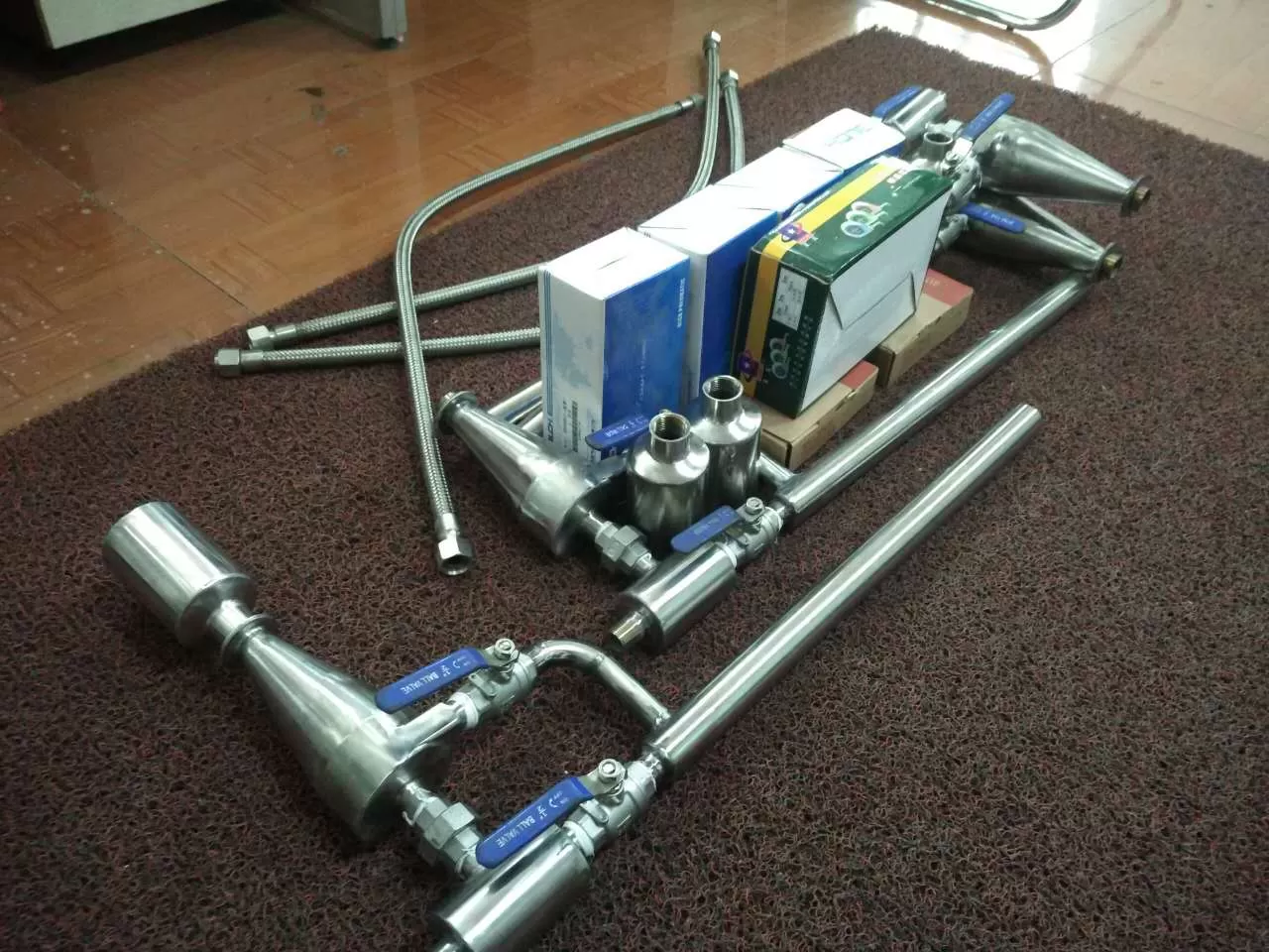
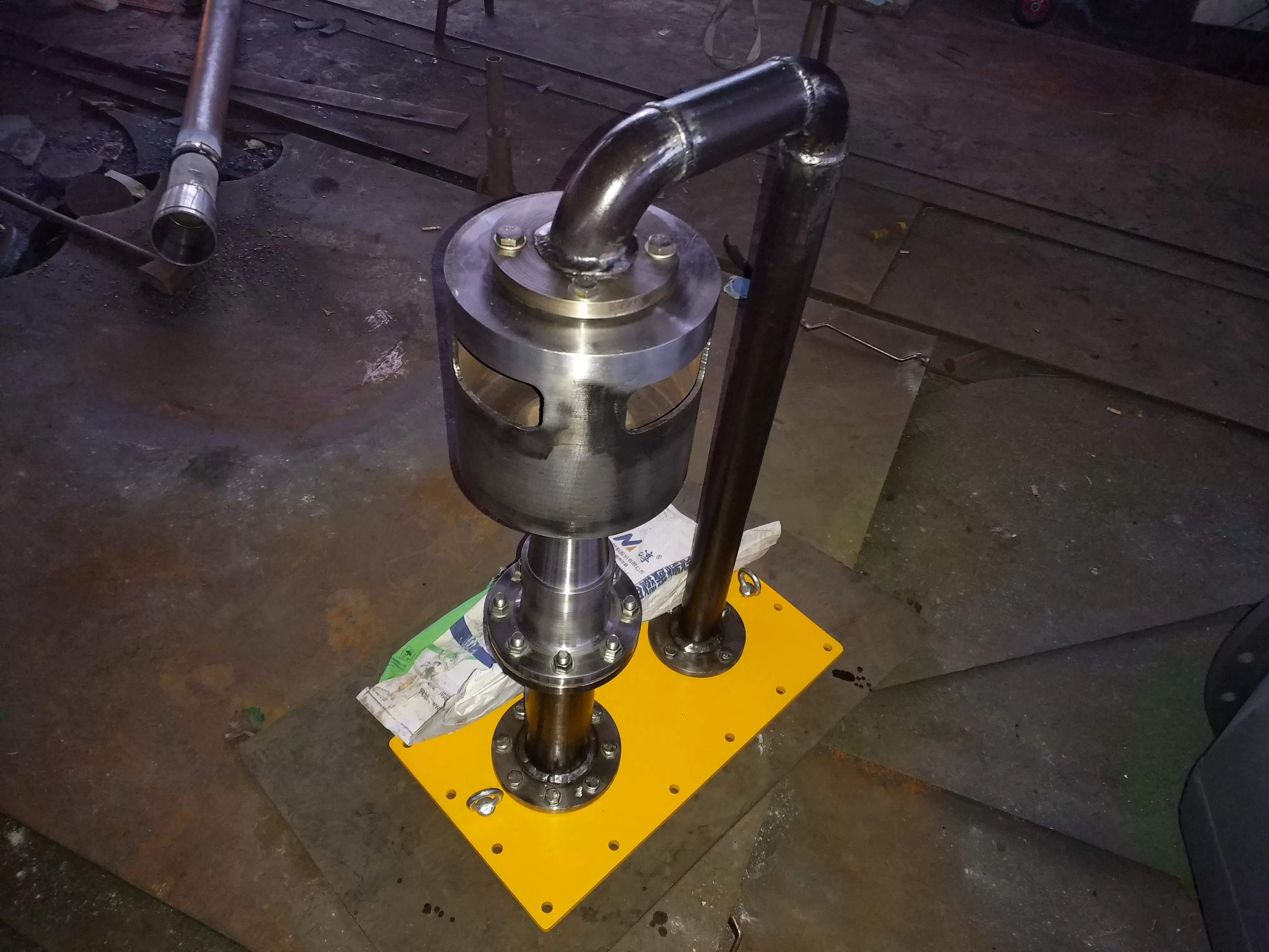
Oil fume exhaust device structure -
In response to the defect of the transmission fan, it has been changed from "horizontal" to "vertical", with an oil drainage circuit inside, and there will be no oil accumulation inside the volute; The motor is connected to the volute as a body, and the sealing between the impeller shaft and the volute is changed from dynamic sealing to static sealing, making it easy to seal; The filter type separator made of materials has replaced the old spiral structure, and the oil fume separation has been fundamentally improved, meeting the requirements of civilized production; In response to the drawback that the impeller and volute of the transmission fan are both made of steel and are prone to sparks, a lightweight aluminum alloy material is used to make the impeller, which avoids the generation of sparks and prolongs the use of bearings and motors.
Due to changes in the amount of oil smoke and steam generated by the unit during operation and time, the constant speed operation of the motor is unreasonable and will consume energy. Our company has developed a high intelligent oil fume exhaust device with a variable frequency speed control system, which can monitor the negative pressure of the oil tank, operate in a closed loop, automatically adjust the fan speed, and maintain a micro negative pressure state of around -300Pa in the main oil tank and bearing box. It can also be designed according to the actual situation of the power plant, with corresponding DCS interfaces reserved. The bearing box system can be equipped with a single high leakage oil fume exhaust device to timely discharge oil fume and shaft seal steam, It not only prevents oil from entering the water, but also prevents oil from flowing out of the bearing box due to positive pressure.
Brief description of the oil fume exhaust device:
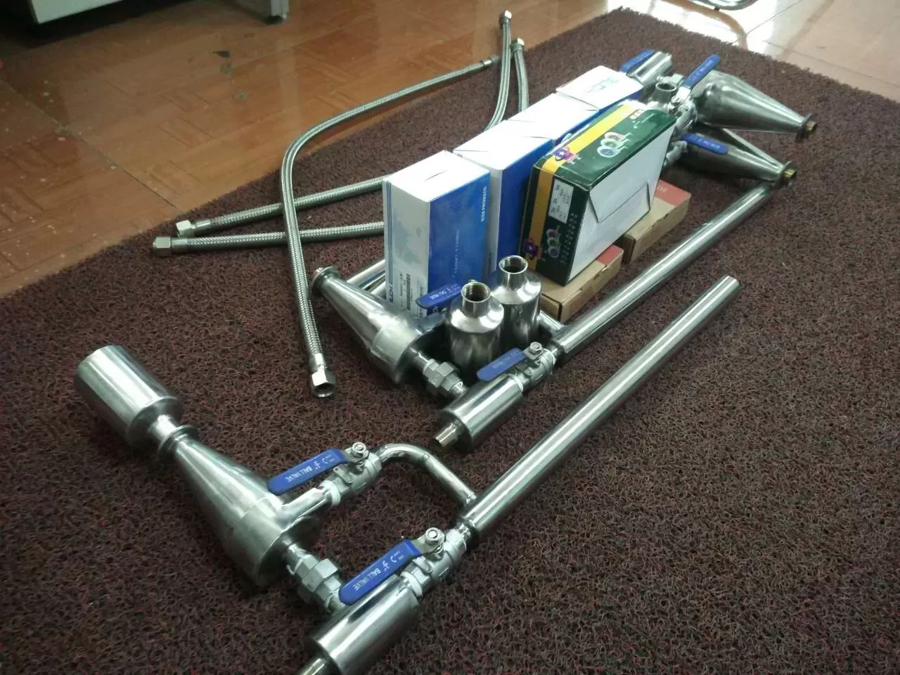
1. The GPY series high leakage oil fume exhaust device is suitable for thermal power plants. In addition to being used on the main oil tank and bearing box of 6MW~800MW steam turbines, it can also be used in various auxiliary equipment (such as feedwater pumps, forced draft fans, induced draft fans, etc.).
2. For units above 100MW, a set of main oil tanks and a set of bearing boxes are used. Adding connecting doors between the two devices is beneficial for their maintenance, while the other set can carry two systems for operation.
3. Generator - oil sealing system - equipped with anti type oil fume exhaust device, one in operation and one in standby.
4. This series is a complete set of oil fume exhaust devices, which cannot be separated or reduced arbitrarily, otherwise it will not achieve the desired effect.
Technical parameters of high oil fume discharge device:
1. The vibration limit of the fan shall comply with the requirements of JB/T8689-1998.
2. The noise limit of the fan shall be in accordance with the JB/T8690-1998 standard.
3. Model definition
GPY oil fume exhaust device - Fan category - Motor type - Turbine power
Note: "GPY" represents the oil fume exhaust device; The category of fans is divided into two types: intelligent type and ordinary type. Intelligent type is represented by "T", while ordinary type is not marked; "Motor category" is divided into two types: anti type and ordinary type. Anti type is represented by "HB", while ordinary type is represented by "II"; The unit of "turbine power" is MW, which is indicated in Arabic numerals and omitted.
Example 1: GPY-T-HB-125 represents an intelligent oil fume exhaust device suitable for 125MW units, equipped with anti electric motors;
Example 2: GPY - Ⅱ -200 represents a high turbine oil fume exhaust device suitable for 200MW units, equipped with non anti electric motors. Its GXP oil fume exhaust device.
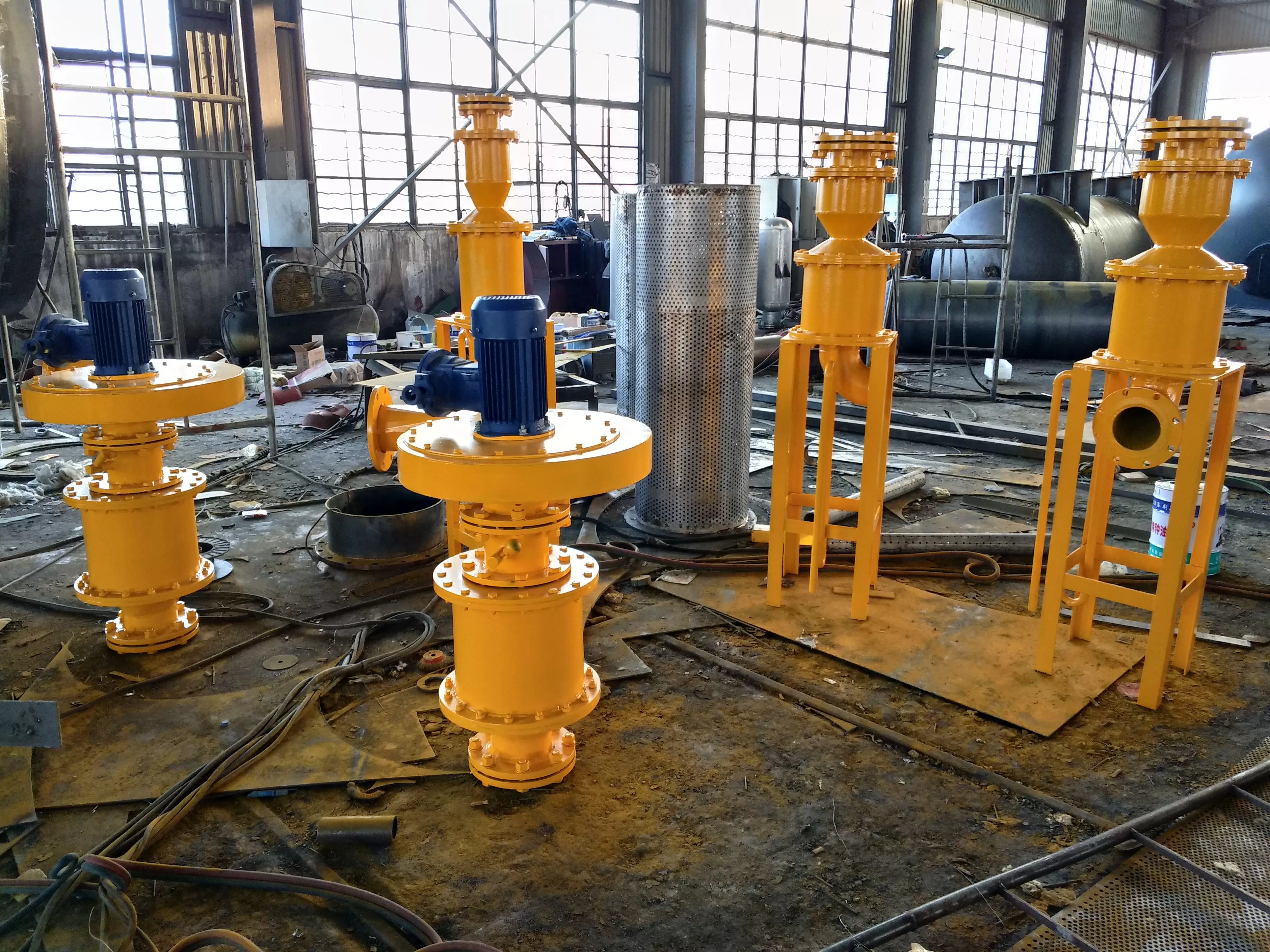
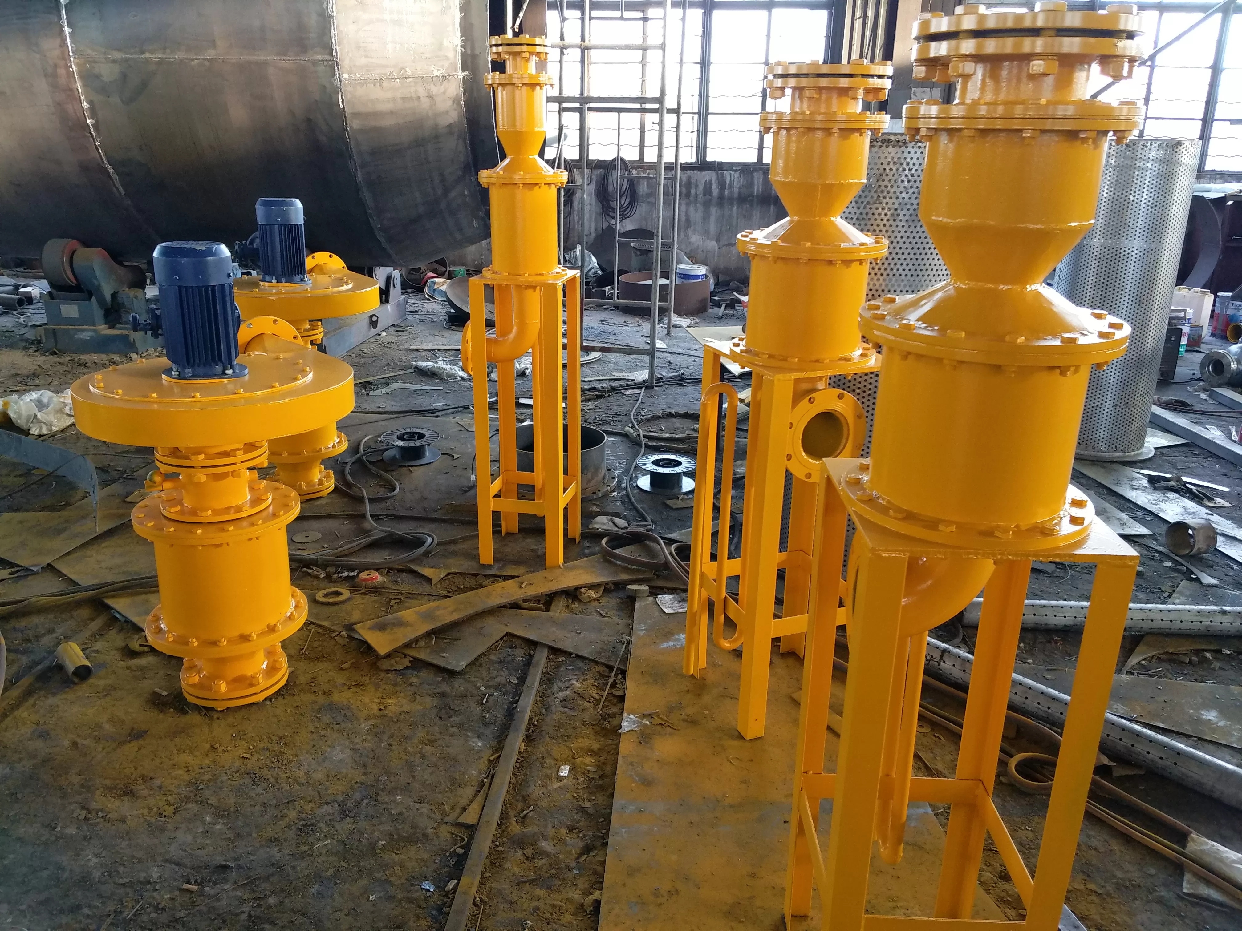
The layout of GXP oil fume exhaust device:
According to the international situation, for oil fans, the original fan can be directly removed and installed according to our installation method. It can be used as a backup or two fans can be operated simultaneously.
-Special specifications can be arranged separately according to user needs for design schemes! Interested parties contact us!
1. Basic parameters of oil fume exhaust device
规格
型号 | 适用机组(MV) | 功率(KW) | 转速
(rpm) | 风量
(m3/s) | 全压
(pa) | 分离器
尺寸 | 排烟管口径 | 备注 |
| GXP-II | 12~25 | 2.2 | 2840 | 0.300 | 3500 | Φ219 | Φ108/133 | 可以在风机进出口加装变径管以适合电厂实际管径
HB系列适用于氢冷机组的-封系统 |
| GXP-II | 50~100 | 3 | 2880 | 0.320 | 4000 | Φ273 | Φ133/159 |
| GXP-II | 125~800 | 4 | 2890 | 0.386 | 5000 | Φ325 | Φ133/159 |
| GXP-HB | 12~200 | 3 | 2880 | 0.320 | 4000 | Φ273 | Φ133/159 |
| GXP-HB | 300~800 | 4 | 2890 | 0.386 | 5000 | Φ325 | Φ133/159 |
| GXP-HB | 特殊要求 | 2.2 | 2840 | 0.300 | 3500 | Φ219 | Φ108/133 |
| GXP-F | 液力耦合
器等辅机 | 0.37 | 2800 | 0.27 | 950 |
|
|
2、风机振动限值按JB/T8689-1998规定要求。
3、风机噪-限值按JB/T8689-1998标准-。
注意:以上产品外形尺寸技术规格参数仅供参考以实际设计为主。