Introduction to tubular heat exchangers:
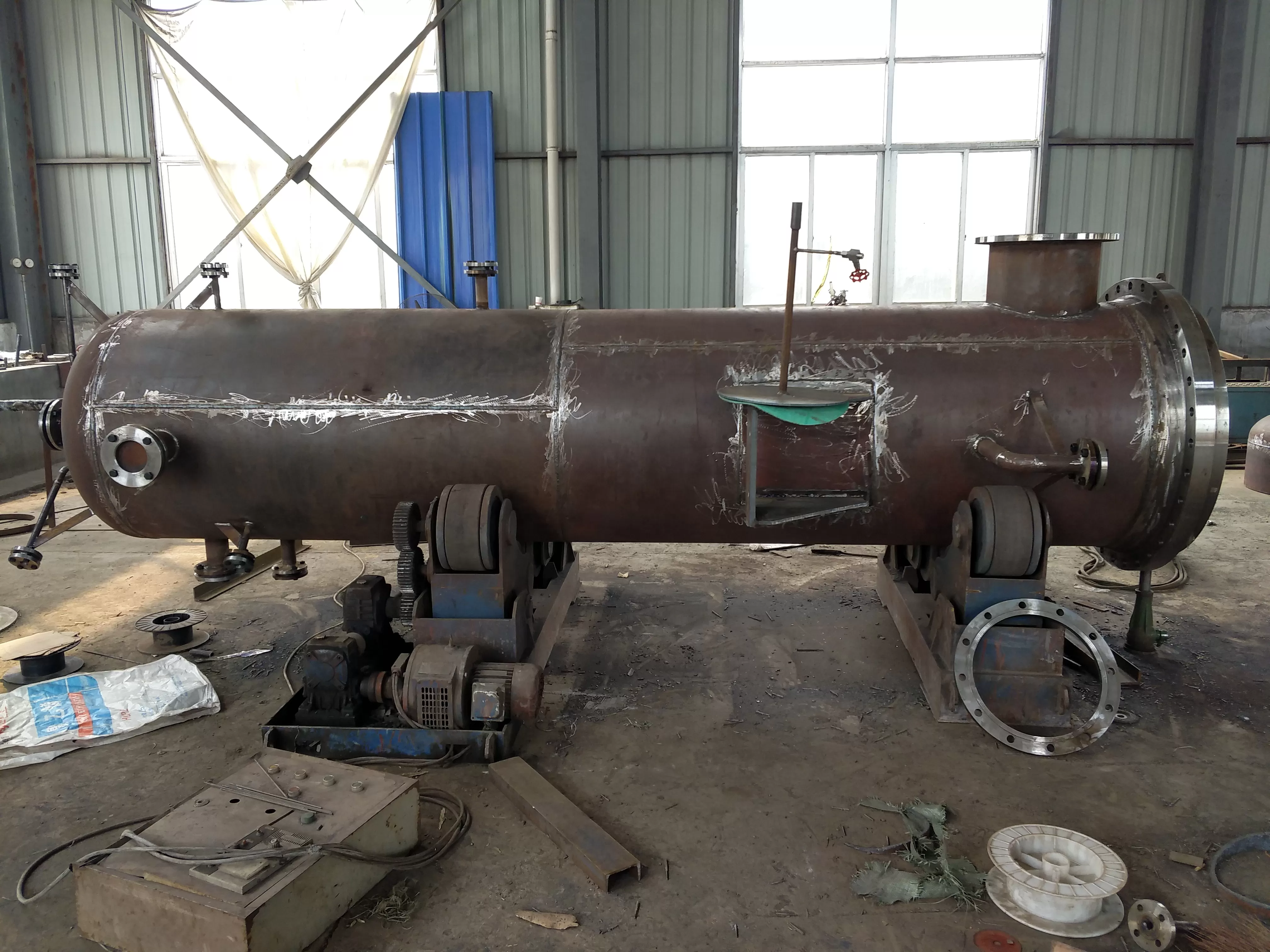
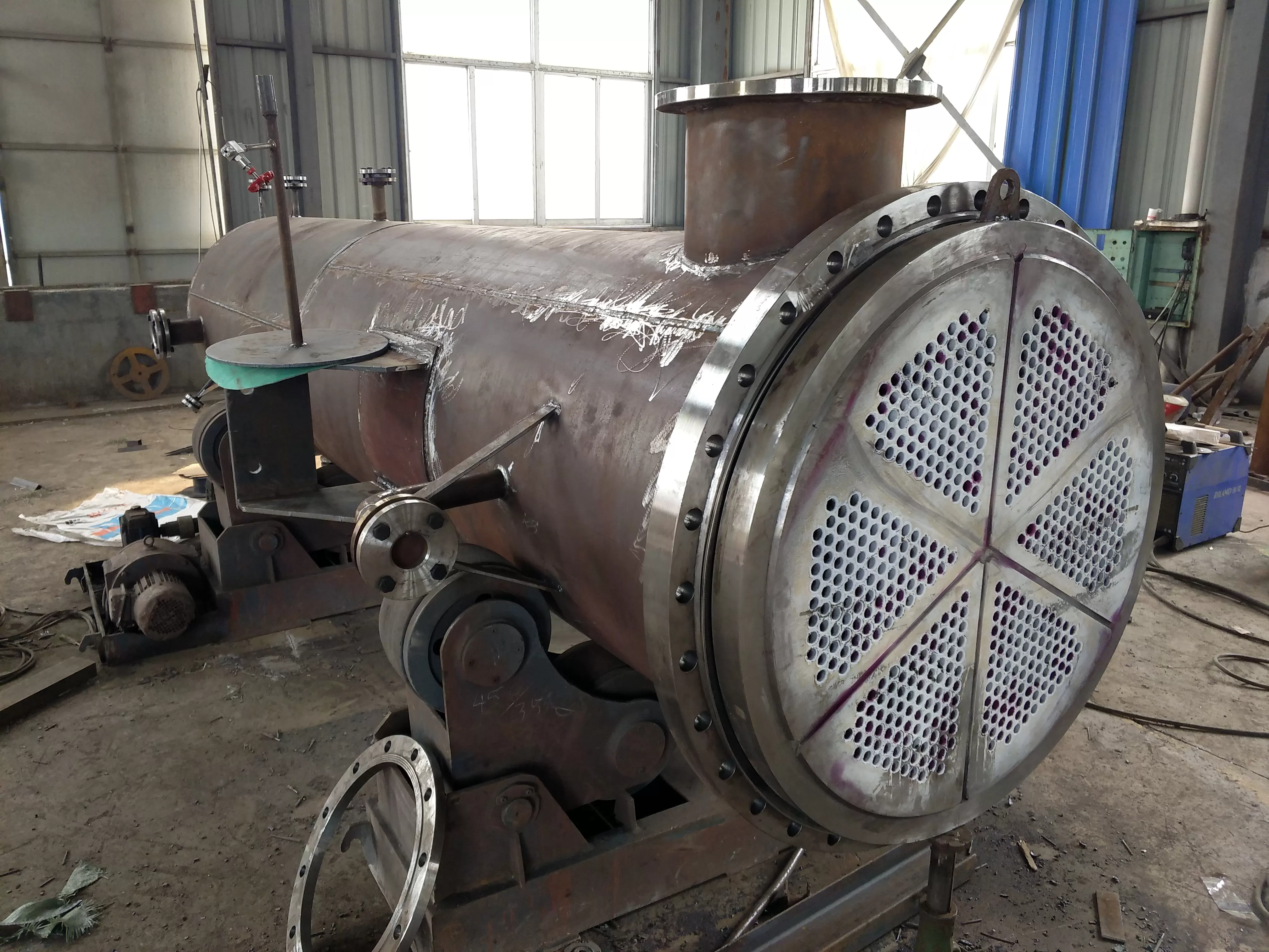
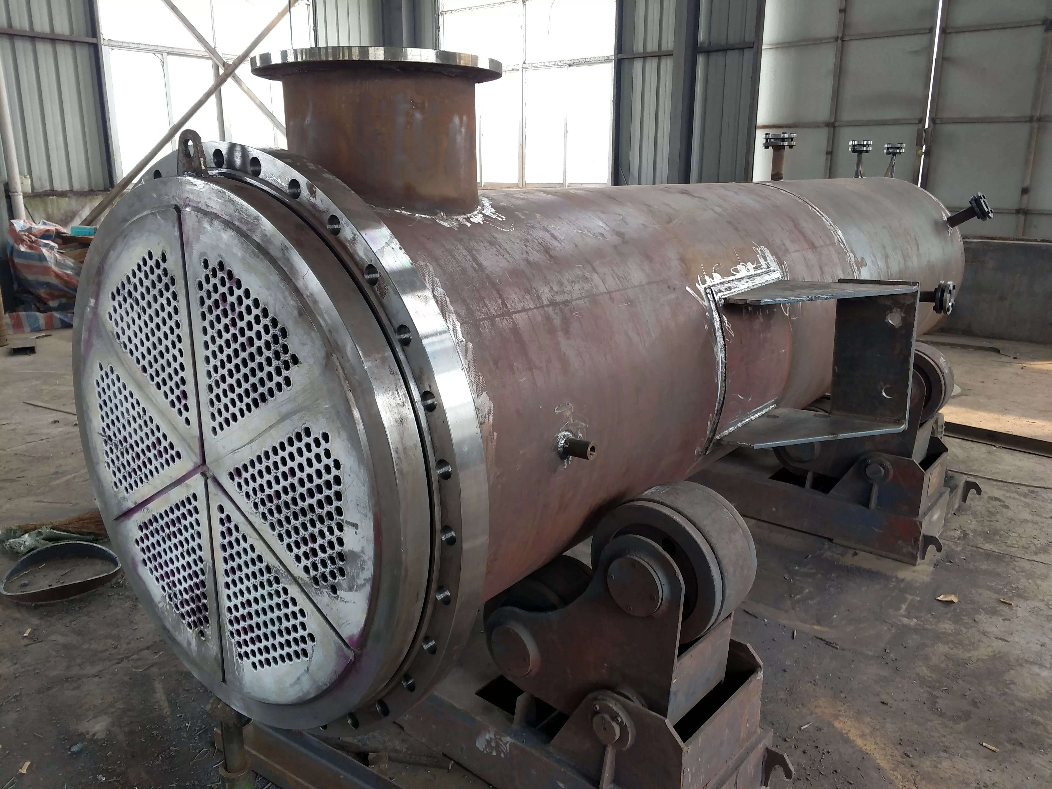
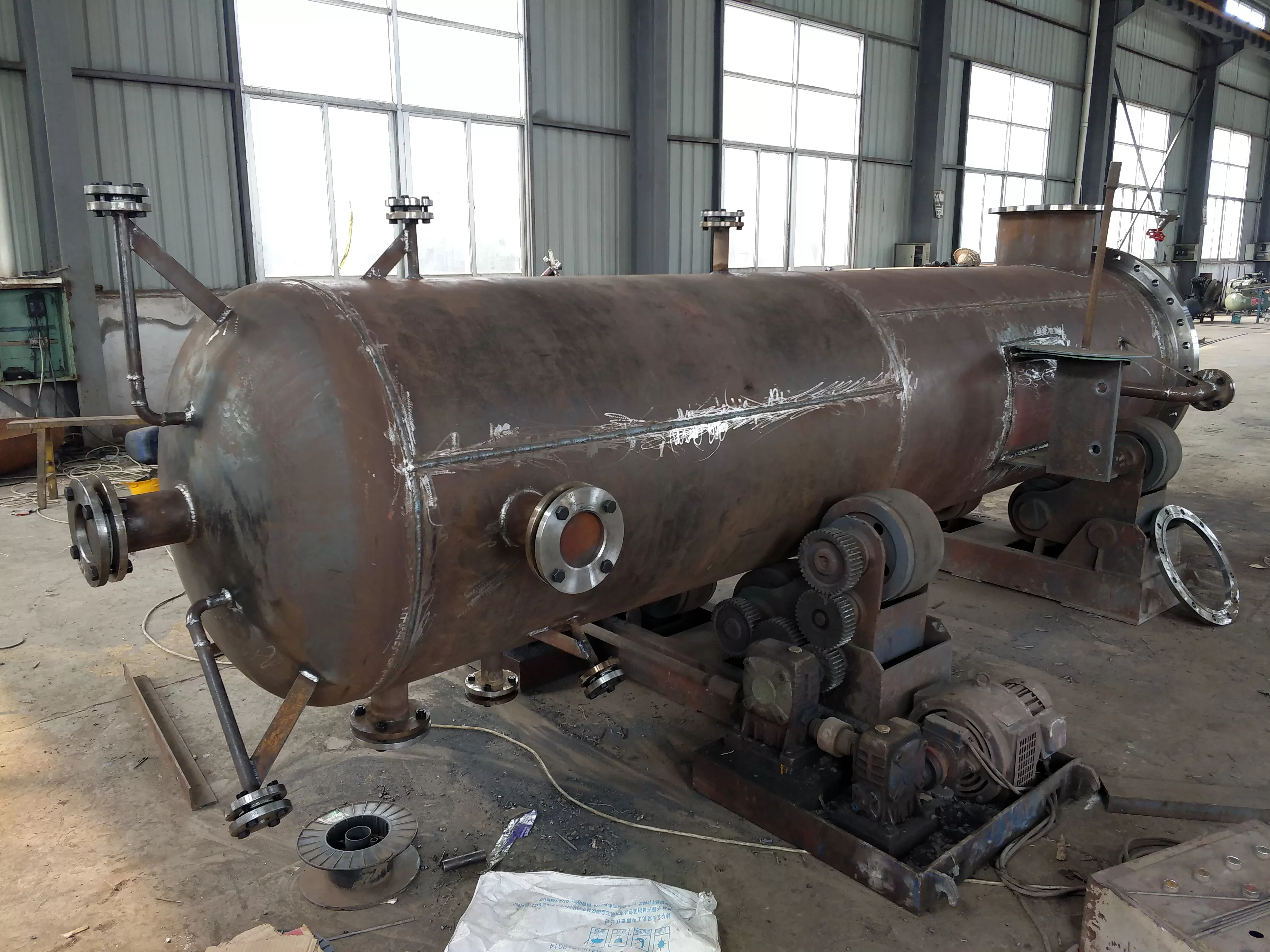
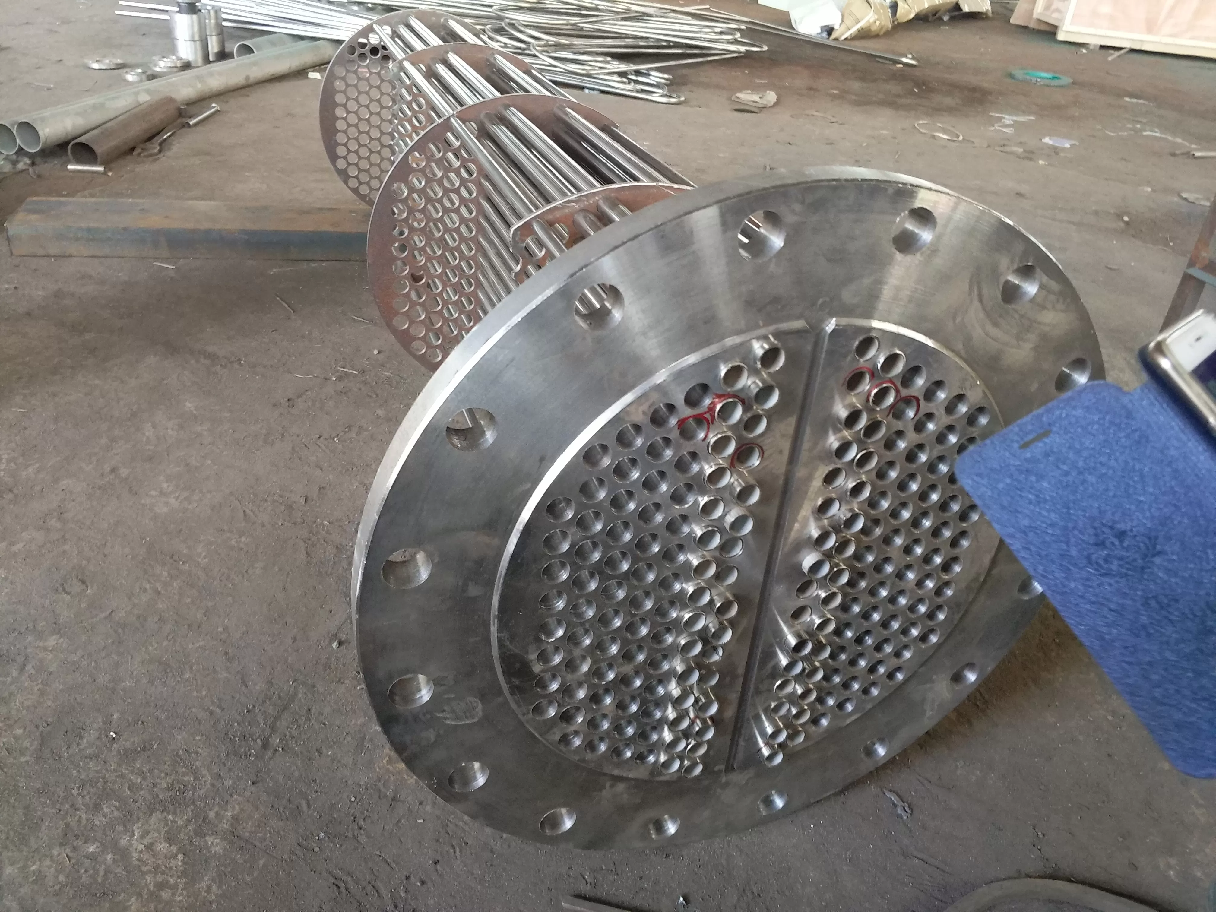
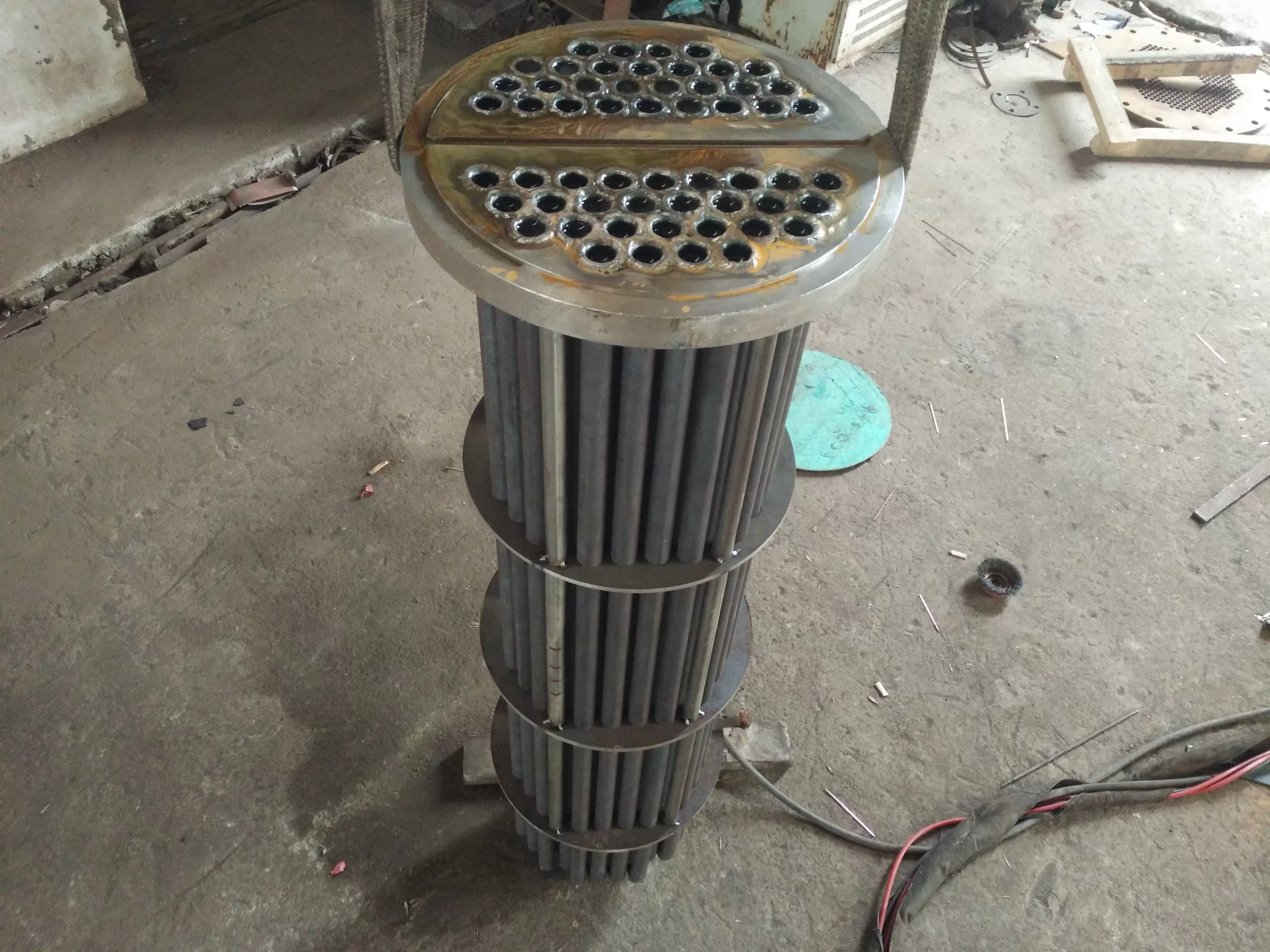
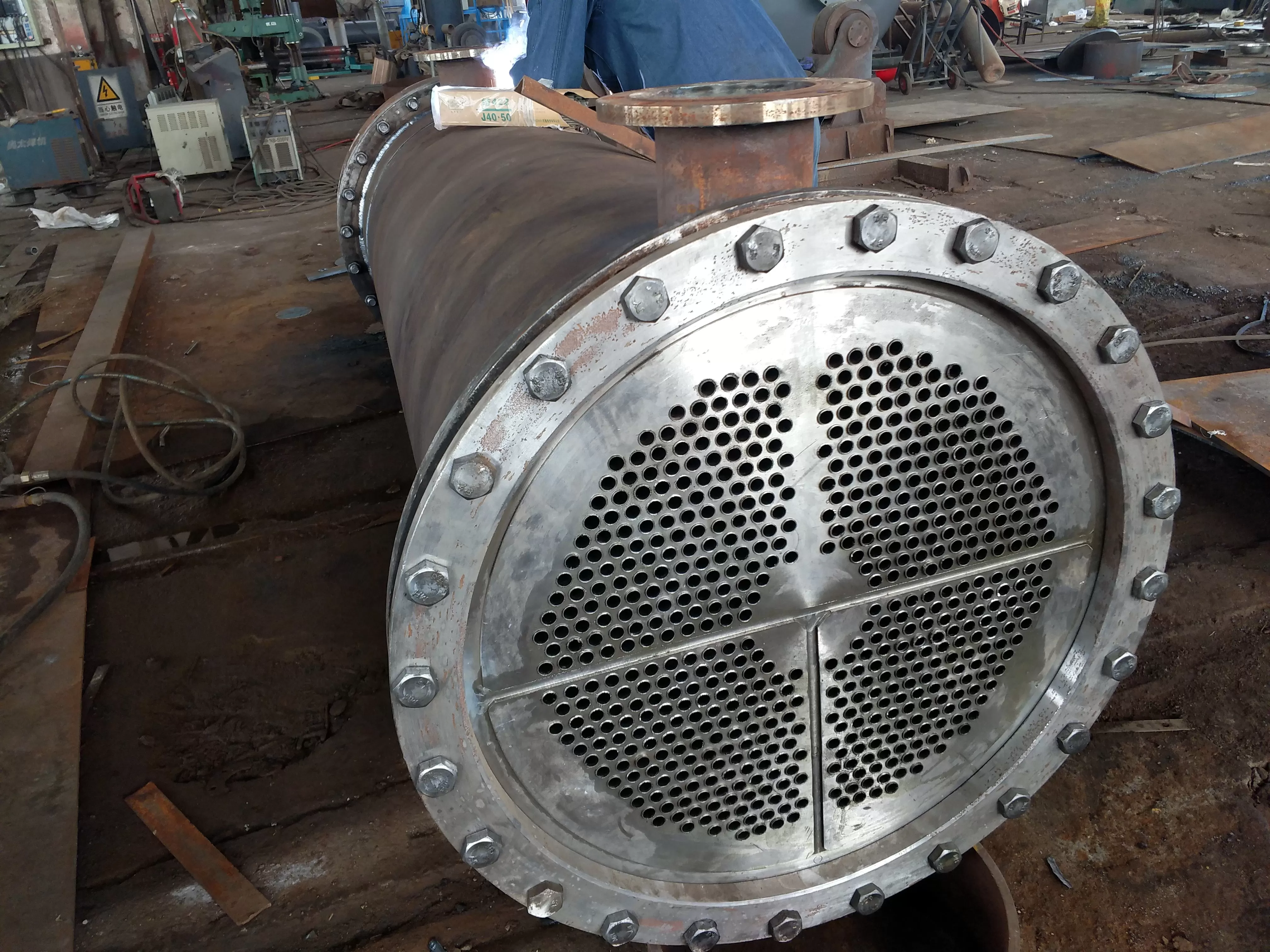
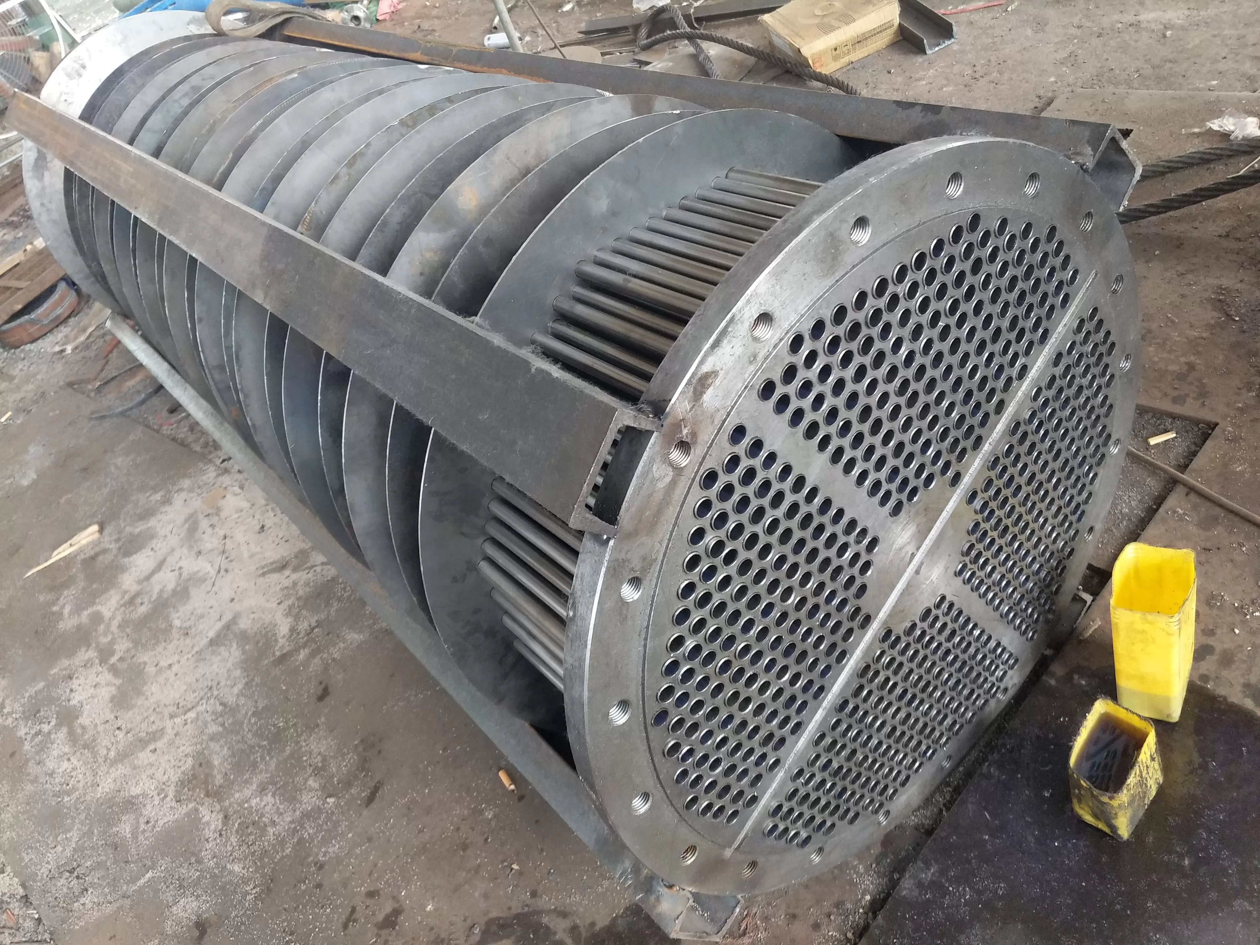
Tubular heat exchanger is a type of heat exchanger widely used in chemical and alcohol production. A tubular heat exchanger mainly consists of a shell, a tube plate, heat exchange tubes, a head, and a baffle. The required materials can be made of ordinary carbon steel, purple copper, or stainless steel respectively. When conducting heat exchange, a fluid enters from the connecting pipe of the head, flows in the pipe, and flows out from the outlet pipe at the other end of the head, which is called the tube side; Another type of fluid enters through the connecting pipe of the shell and flows out from the other connecting pipe on the shell, which is called the shell side.
Various types of heat exchangers:
Fixed tube plate type
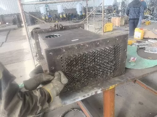
The structure of a tubular heat exchanger is relatively simple, compact, and manufactured, but the outside of the tube cannot be mechanically cleaned. This type of heat exchanger tube bundle is connected to a tube plate, which is welded to both ends of the shell and connected to a cover. The cover and the shell are equipped with fluid inlet and outlet connections. A series of baffles perpendicular to the tube bundle are installed outside the tube. At the same time, the connection between the pipe and the shell is rigid, while the inside and outside of the pipe are two different fluids at different temperatures. Therefore, when the temperature difference between the pipe wall and the shell wall is large, due to the different thermal expansion of the two, a large temperature difference stress is generated, which can cause the pipe to twist or loosen from the pipe plate, and even damage the heat exchanger.
In order to overcome temperature difference stress, a temperature difference compensation device is required. Generally, when the temperature difference between the pipe wall and the shell wall is more than 50 ℃, for safety reasons, the heat exchanger should have a temperature difference compensation device. But the compensation device (expansion joint) can only be used in situations where the temperature difference between the shell wall and the pipe wall is -60-70 ℃ and the fluid pressure on the shell side is not high- When the pressure on the shell side exceeds 0.6Mpa, due to the thick compensation ring, it is difficult to expand and lose the function of temperature difference compensation. Therefore, other structures should be considered.
Floating head type
A piece of tube plate of a heat exchanger is connected to the shell with a flange, while another piece of tube plate is not connected to the shell, so that the tube can freely expand and contract when heated or cooled. However, a cover is connected to this tube plate, which is called a "floating head", so this type of heat exchanger is called a floating head heat exchanger. It is: the tube bundle can be pulled out for cleaning; The expansion of the tube bundle is not constrained by the shell, so when the temperature difference between the two heat exchanger media is large, there will be no temperature difference stress due to the difference in thermal expansion between the tube bundle and the shell. Its shortcomings are complex and high.
Stuffing box type
This type of heat exchanger bundle can freely expand at the end, with a simpler structure and lower cost compared to the floating head type. However, there is a possibility of external media inside the shell side, and volatile, flammable, flammable, and hazardous media should not be handled in the shell side.
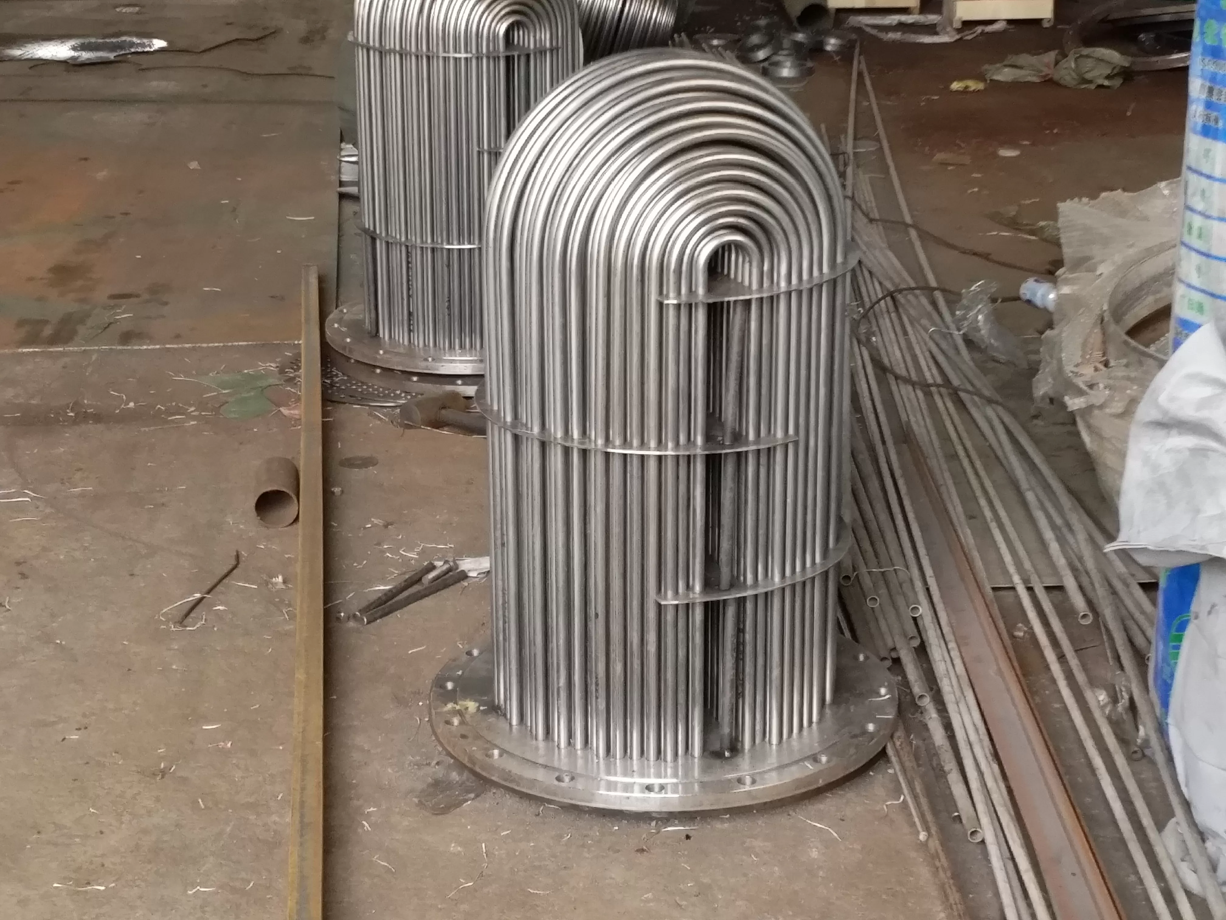
U-shaped tube type
Each tube of a U-shaped heat exchanger is bent into a U-shape, with both ends fixed on the same tube plate. Each tube can freely expand and contract, thus solving the problem of thermal compensation. The tube has at least two passes, the tube bundle can be removed for cleaning, and the tube can expand freely. Its shortcomings include difficulty in cleaning the inner wall of the pipe, difficulty in replacing the pipe, and fewer pipes arranged on the pipe plate-- It is simple and lightweight, suitable for high temperature and high pressure conditions.
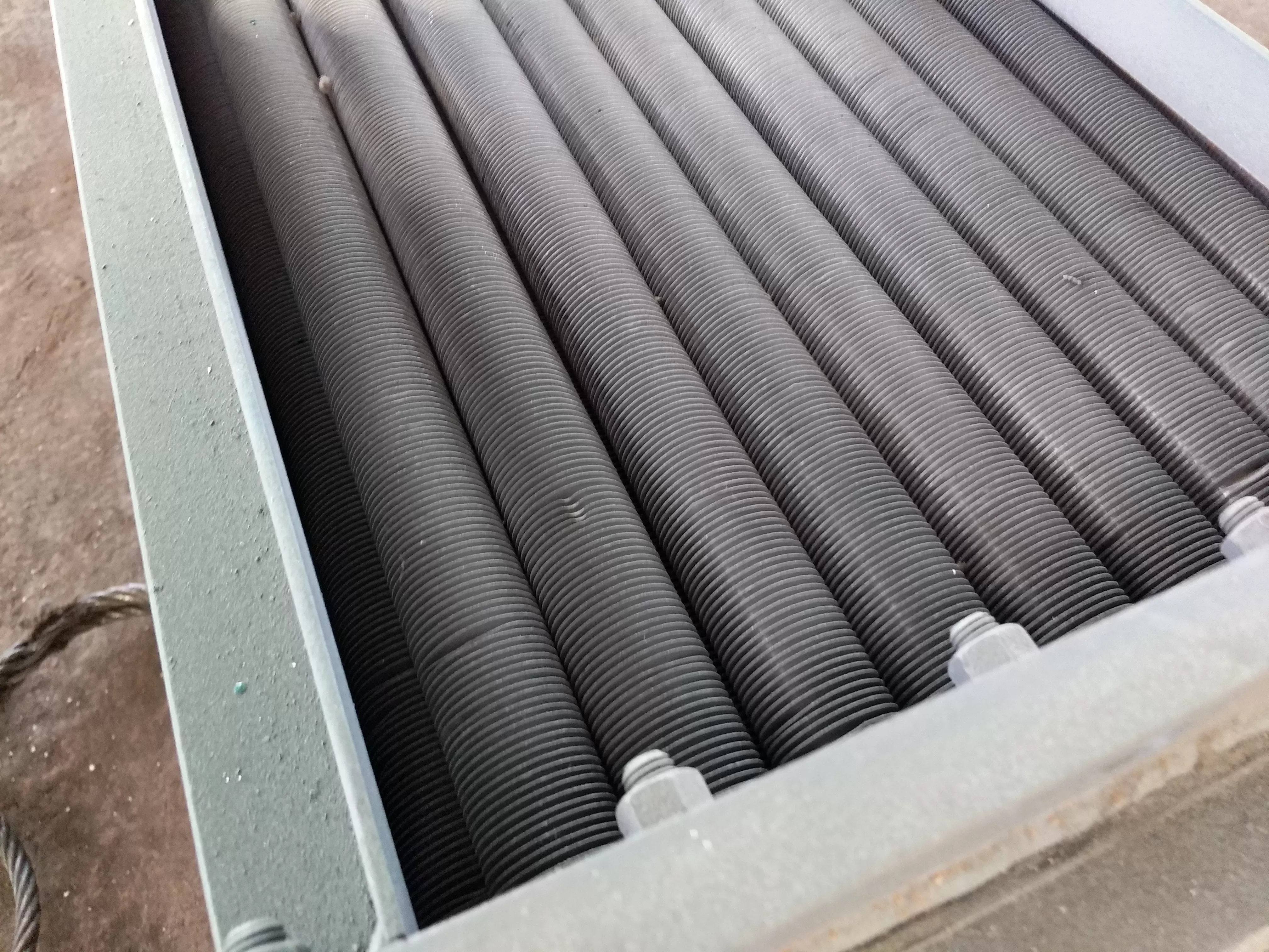
Eddy current hot film
The vortex hot film heat exchanger adopts the vortex hot film heat transfer technology, which increases heat transfer by changing the fluid motion state. When the medium passes through the surface of the vortex tube, it strongly washes the surface of the tube, thereby improving the heat transfer rate- Up to 10000W/m2 ℃. At the same time, this type of structure exhibits corrosion, high temperature, high pressure, and anti scaling functions. The fluid channel of other types of heat exchangers adopts a fixed directional flow form, forming a flow around the surface of the heat exchange tube and reducing the convective heat transfer coefficient.
According to the data from Guangxin, the advantage of vortex heat film heat exchangers lies in their economy and safety. Due to the consideration of the flow relationship between the heat exchange tubes and between the heat exchange tubes and the shell, turbulence is no longer forced out by baffle plates. Instead, alternating vortex flows are naturally induced between the heat exchange tubes, and the necessary vibration force is maintained while ensuring that the heat exchange tubes do not rub against each other. The rigid and flexible configuration of the heat exchange tubes is good, and they will not collide with each other, which not only overcomes the problem of damage caused by collision between floating coil heat exchangers, but also avoids the problem of scaling in ordinary shell and tube heat exchangers.
Eddy current hot film heat exchanger - Energy -:
1. High energy-saving, the heat transfer coefficient of this heat exchanger is 6000-8000W/m2.0C;
2. Made of all stainless steel, with a lifespan of over 20 years. If there are problems with the heat exchanger within 10 years, it will be replaced at a cost;
3. Changing laminar flow to turbulence improves heat transfer efficiency and reduces thermal resistance;
4. Heat exchange rate -, - high temperature (400 ℃), - high pressure (2.5Mpa);
5. Compact structure, small footprint, light weight, convenient installation, and saving on civil engineering investment;
6. Flexible design, complete specifications, targeted use, and cost saving;
7. Application conditions - suitable for a wide range of pressure, temperature, and heat exchange of various media;
8. Low maintenance cost, easy operation, long cleaning cycle, and convenient cleaning.
9. Adopting nano thermal film technology to increase heat transfer coefficient.
10. With a wide range of applications, it can be used in fields such as thermal power, factories and mines, petrochemicals, urban heating, food, energy electronics, machinery and light industry, etc.
Eddy current hot film heat exchanger - energy compar删除n:
| 对比项目 | 浮动盘管换热器 | 螺纹管换热器 | 涡流热膜换热器 |
| 适用介质种类 | 蒸汽、水 | 蒸汽、水 | 弱腐蚀-化工原料、蒸汽、水 |
| 介质的参数范围 | 温度:0-150度
压力:0-1.0MPa | 温度:0-150度
压力:0-1.6MPa | 温度:-40-400度
压力:0-10.0MPa |
| 热-率 | 热-率=92% | 热-率=93% | 热-率=96% |
| 防垢遥遥能 | 自动除垢 | 人工除垢 | 具有防垢功能 |
| -震、噪- | 振动较大,噪-大 | 振动较小,噪-小 | 振动微弱,噪-小 |
| 试用- | 7年左右 | 10年左右 | 20年左右 |
| 维修 | 停机维修,-换管束 | 停机维修,拔管再胀管 | -需维修
|
Baffle
To improve the flow velocity of the shell side fluid, a certain number of baffle plates perpendicular to the tube bundle are often installed inside the shell. Baffles not only prevent fluid short circuits and increase fluid flow velocity, but also force the fluid to cross flow through the tube bundle according to the specified path, greatly increasing turbulence- There are two types of baffle plates used: circular and circular, which are used.
-Shell process
Tubular heat exchangers must consider the impact of thermal expansion from a structural perspective, adopt various compensation methods to eliminate or reduce thermal stress, and take temperature difference compensation measures according to the adopted ones.
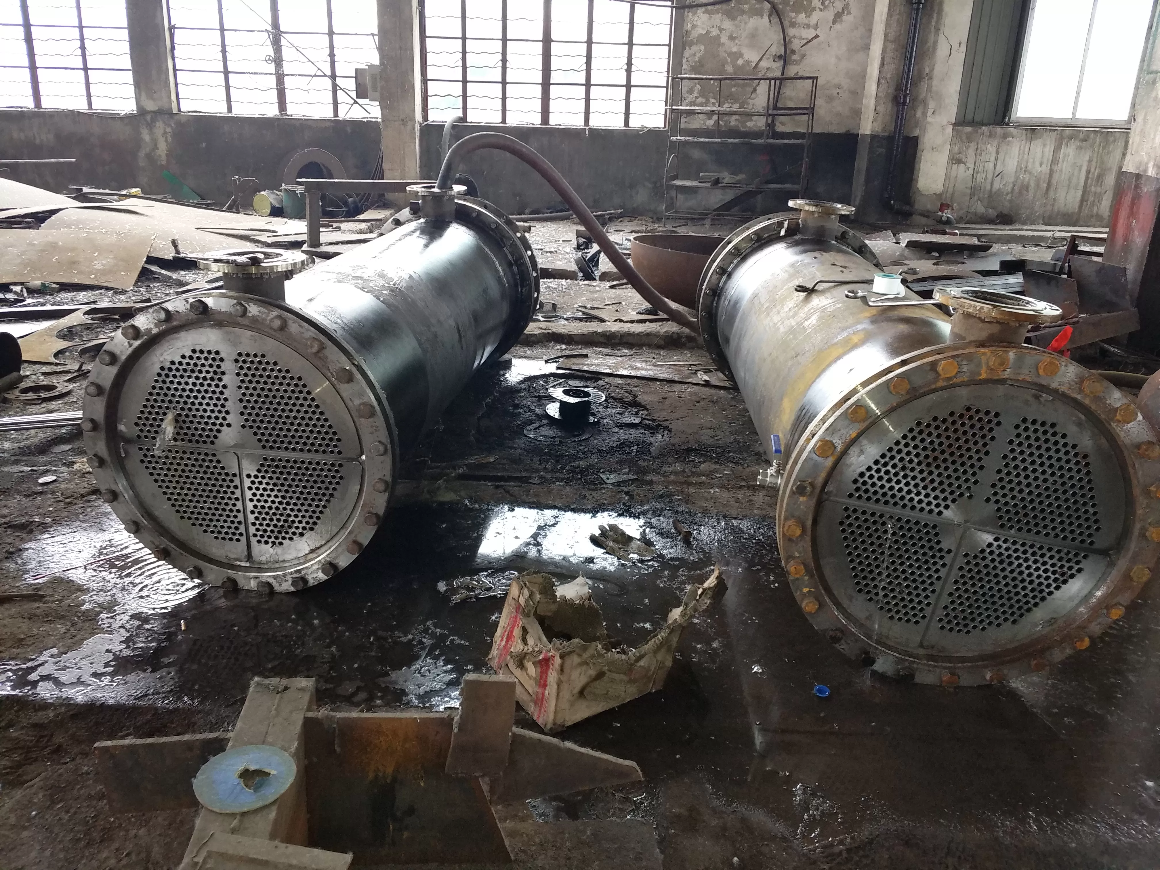
Infiltration analysis:
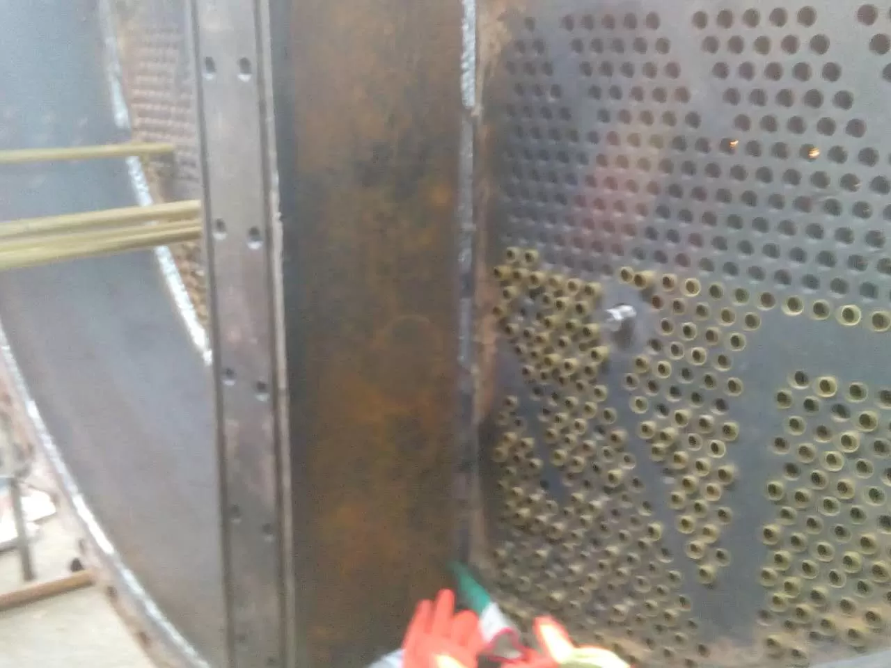
Heat exchanger leakage is a common equipment management problem in the use of heat exchangers. Leakage is mainly caused by corrosion, and a small part is due to defects in the selection of heat exchangers and the manufacturing process of heat exchangers themselves. There are basically two forms of corrosion in tubular heat exchangers: electrochemical corrosion and chemical corrosion. During the production of tube and tube heat exchangers, manual arc welding is generally used for the welding between the tube plate and the column. The shape of the weld seam has different degrees of defects, such as dents, pores, slag inclusions, etc., and the distribution of weld stress is also uneven. When in use, the tube plate is generally in contact with industrial cooling water, and impurities, salts, gases, and microorganisms in industrial cooling water can corrode the tube plate and welds. This is what we call electrochemical corrosion. Research has shown that industrial water, whether freshwater or seawater, contains various ions and dissolved oxygen, and the concentration changes of chloride ions and oxygen play a significant role in the corrosion shape of metals. In addition, the complexity of the metal structure can also affect the corrosion morphology. Therefore, the corrosion of the weld between the tube plate and the column is mainly pitting corrosion and crevice corrosion. From the outside, there will be some corrosion products and sediment on the surface of the tube plate, distributed with pits of varying sizes. When using seawater as a medium, galvanic corrosion may also occur. Chemical corrosion is the corrosion of the medium, and when the heat exchanger tube plate comes into contact with various chemical media, it will be corroded by the chemical media. In addition, the heat exchanger tube plate will also produce certain bimetallic corrosion between the heat exchanger tubes- Some tube plates are still subjected to erosion by corrosive media for a long time. Especially for fixed tube plate heat exchangers, there is also temperature difference stress, and the connection between the tube plate and the heat exchange tube is prone to leakage, leading to heat exchanger failure.
-As mentioned above, the main factors affecting the corrosion of heat exchanger tube sheets are:
(1) Medium composition and concentration: The influence of concentration is not significant, for example, in hydrochloric acid, the higher the concentration, the more severe the corrosion. Carbon steel and stainless steel corrode severely in sulfuric acid at a concentration of about 50%, but when the concentration increases to over 60%, the corrosion actually sharply decreases;
(2) Impurities: Harmful impurities include chloride ions, sulfur ions, cyanide ions, ammonia ions, etc. These impurities can cause severe corrosion in some cases
(3) Temperature: Corrosion is a chemical reaction, and for every 10 ℃ increase in temperature, the corrosion rate increases by about 1-3 times, but there are exceptions;
(4) PH value: Generally, the smaller the pH value, the greater the corrosion of the metal;
(5) Flow rate: The higher the flow rate under numerical conditions, the greater the corrosion.
Trial method:
Tubular heat exchanger - loss measurement
In fault testing, especially in the heat exchanger section, industry knowledge and instruments can be used to determine the causes of corrosion phenomena. Here, we take Meijiahua's technical production as an example to understand the functions of the damage testing equipment:
1) Visual endoscope - inner surface of the tube plate;
2) Customized problem research and reporting;
3) APR (Acoustic Pulse Reflection Method), a creative loss measurement technique based on the analysis of dimensional sound waves generated inside the tube plate;
4) - Heat exchanger pipes made of magnetic and magnetic materials, with straight and curved losses;
5) - Speed measurement: Each pipe is less than 10 seconds long;
6) - Testing for leaks, complete and partial blockage, erosion, and corrosion;
7) Suitable for elliptical tubes, square tubes, spiral tubes, ribbed tubes, and bends from a 9/16 "diameter;
8) Immediate visual results;
9) Digital storage is used for future reference and compar删除n.
10) Customized problem research and cost estimation.
The method of water testing
The experiment of using water to heat exchanger is to inject water into the heat exchanger, fill it with water, and then use a water pump to pressurize the water in the heat exchanger to a certain pressure for inspection. Check - mark and release pressure and drain before plugging. If the heat exchanger is large and has strict leakage, leakage will occur when the water pressure is low, and drainage blockage is necessary. After the blockage is completed, water filling and pressure testing can be repeated to increase the repair time of the heat exchanger. Due to the large amount of time required for water filling and pressurization, the leaking area needs to be repaired and welded with hot work, and the leaking area needs to be dried, otherwise it will affect the repair and welding process. If there is combustible medium inside the leaked heat exchanger, nitrogen replacement must be carried out before hot work welding can be carried out, otherwise it will cause fire and endanger personal and equipment safety.
Method of nitrogen testing
After the discharge of the tubular heat exchanger, nitrogen gas is used for pressure testing to compare the speed. When using nitrogen to block or perform hot work on the heat exchanger, no replacement treatment is required to save time for repair and elimination.
The use of nitrogen in the trial of ammonia synthesis heat exchanger
Operation requires-
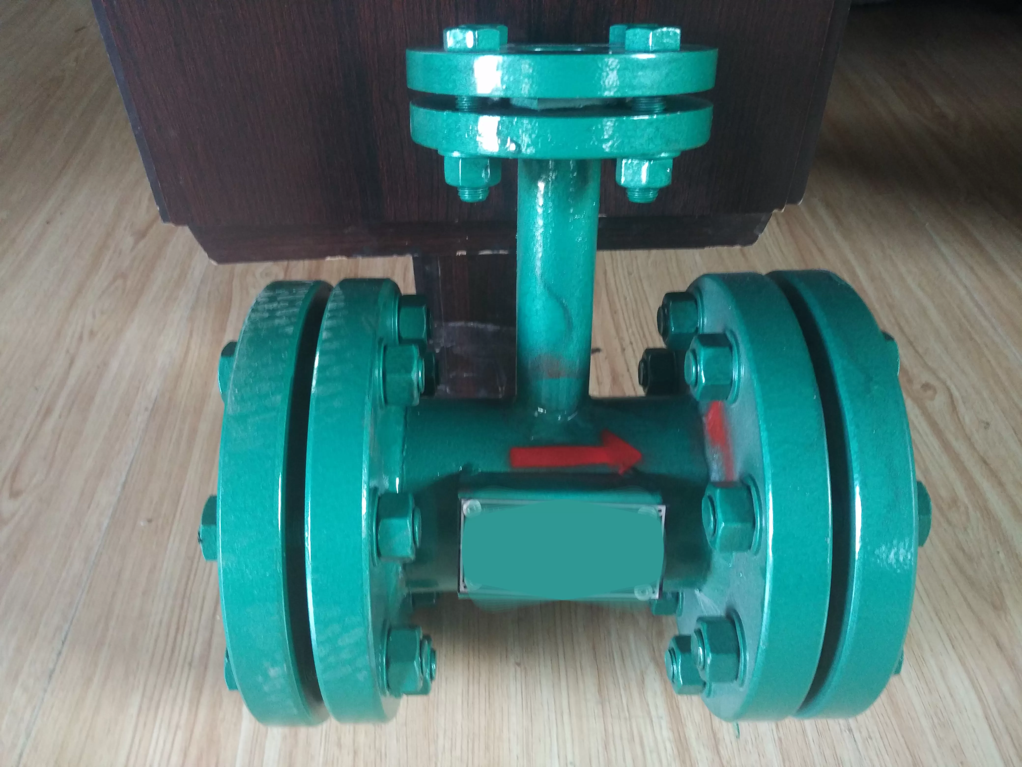
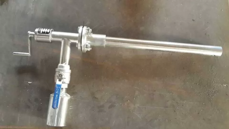
(1) Due to the use of high-pressure nitrogen gas (with a pressure of 9.5MPa), it is necessary to have at least 2 people working to open the valve. A pressure gauge should be installed between the two valves, with one person monitoring the indication of the pressure gauge and another person performing the valve opening operation to ensure that the pipeline pressure is within the allowable range and prevent pressure from causing injury to the pipeline or personnel.
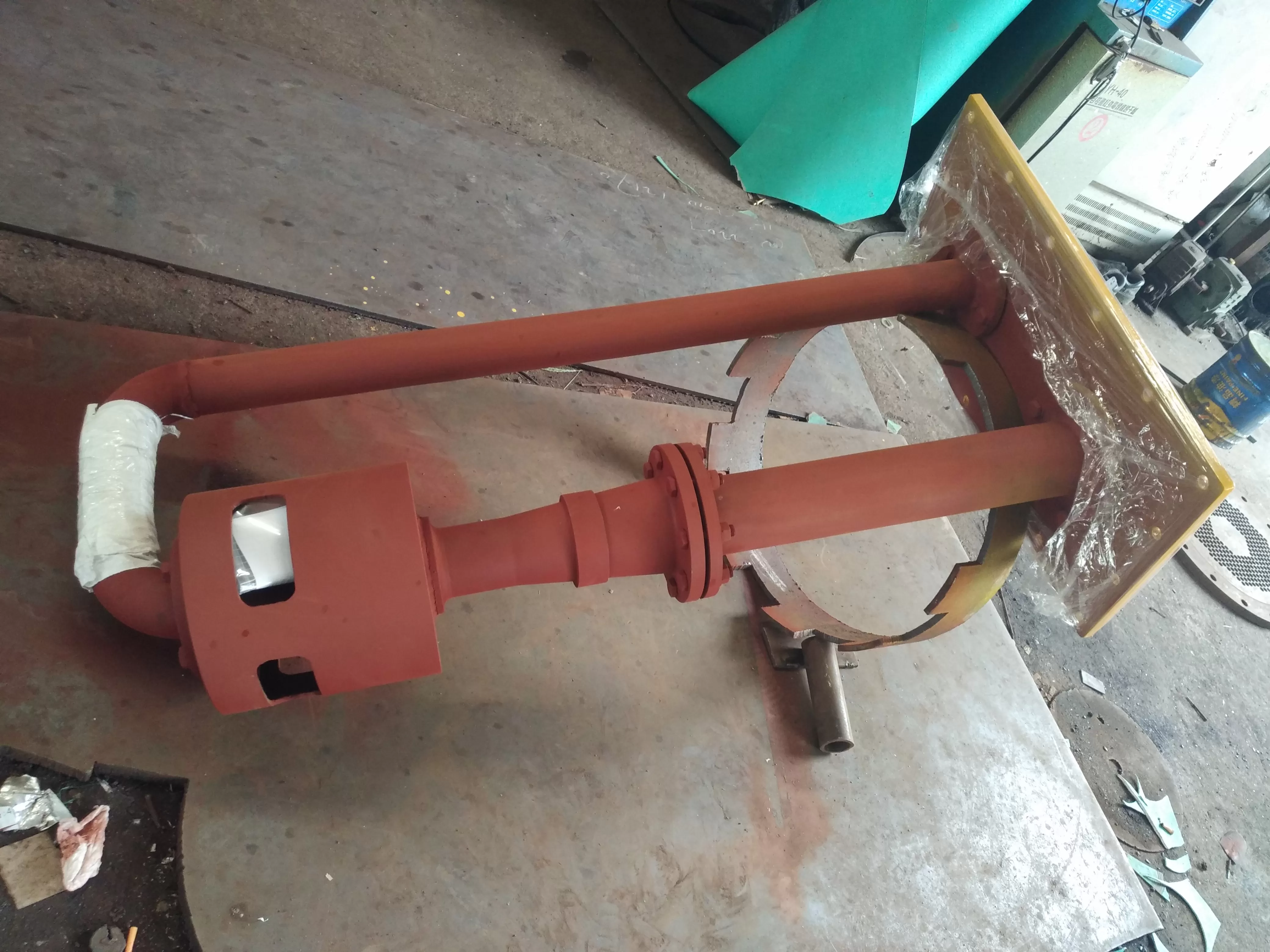
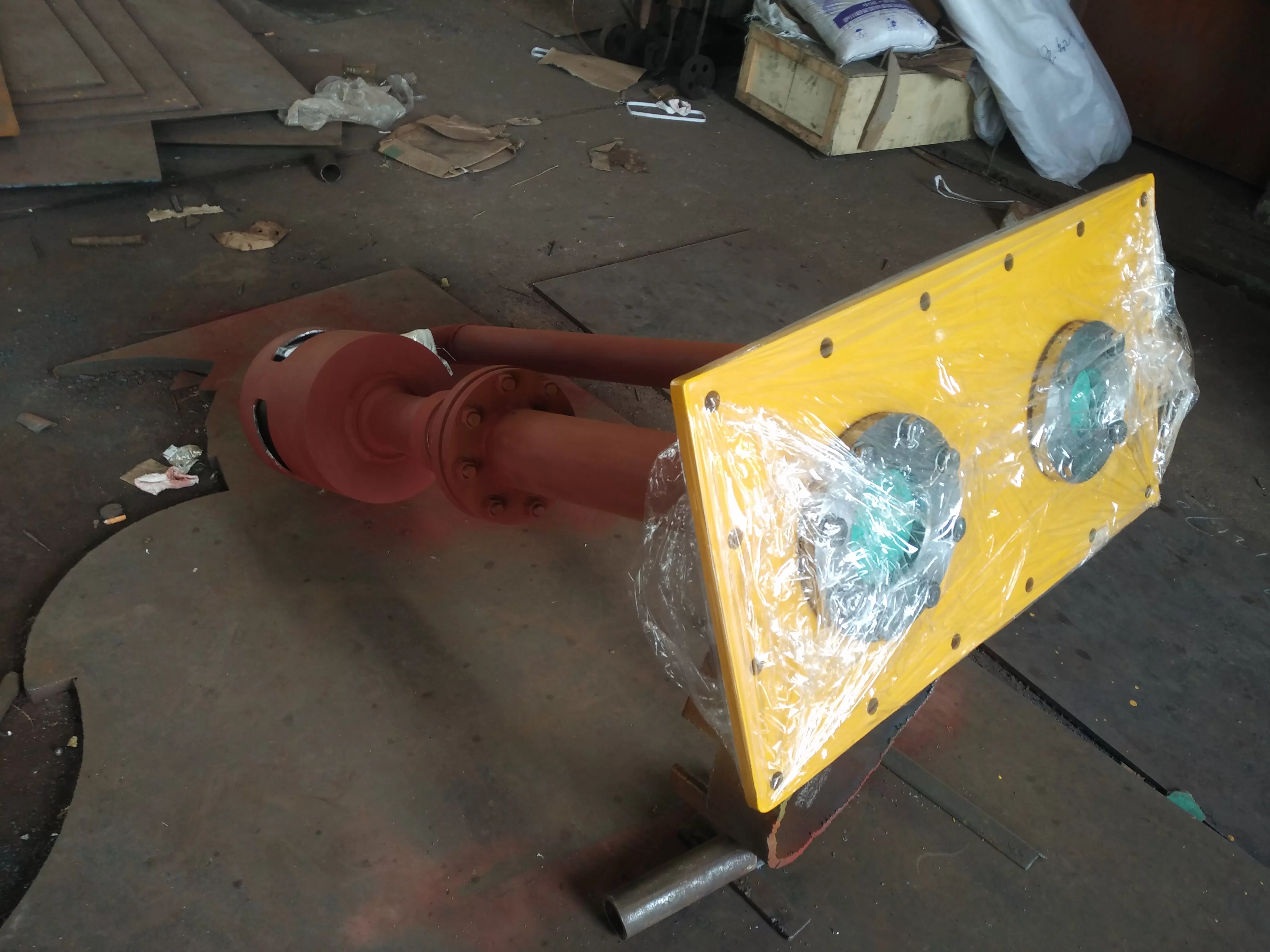
(2) Heat exchanger EA103 is a floating head heat exchanger, and a test head needs to be installed on the heat exchanger during testing.
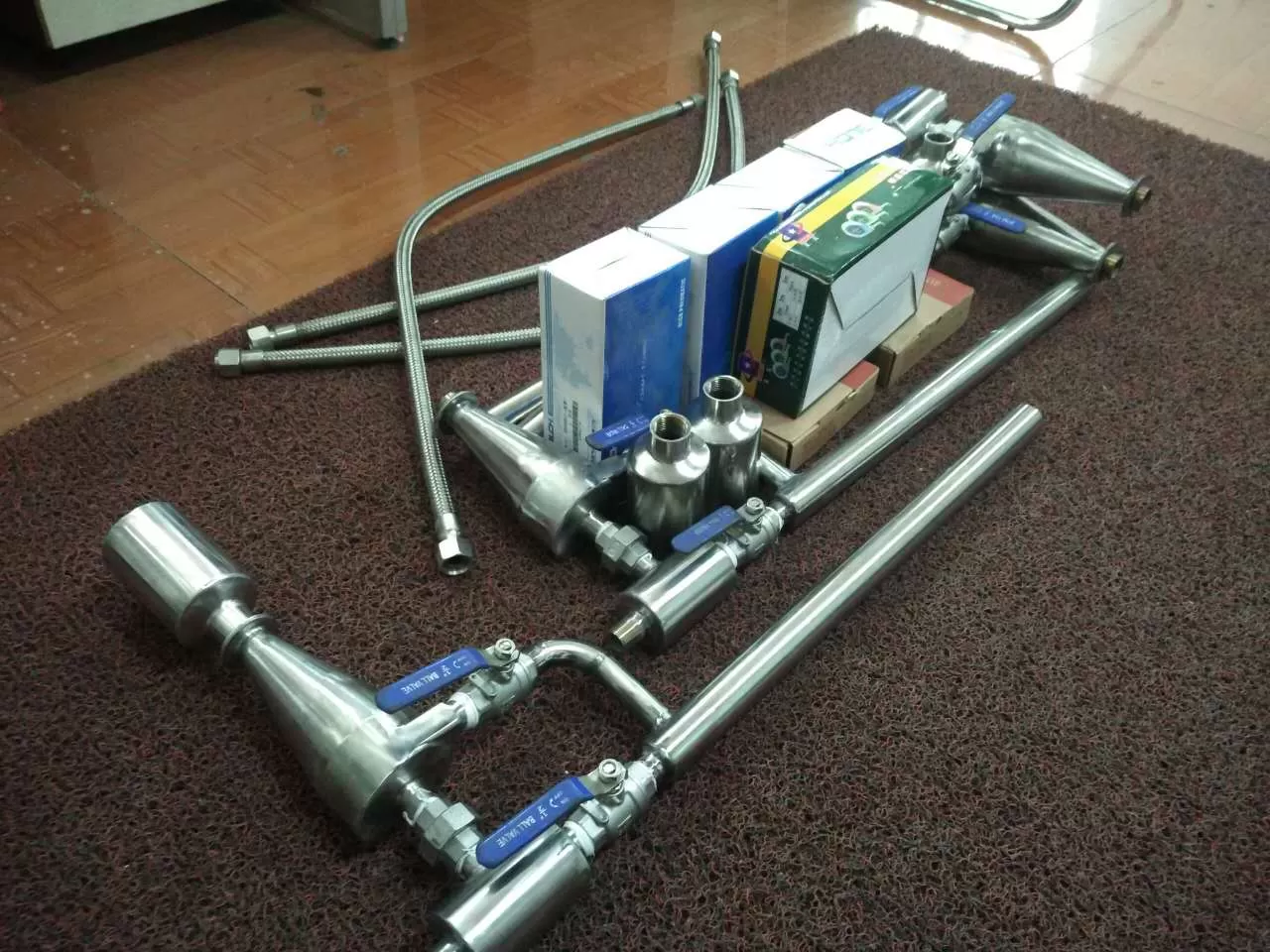
(3) Operation Steps - Fully open valve 1 and valve 3, as shown in Figure 1, then slowly open valve 2 to pressurize the heat exchanger, while paying attention to the pressure gauge pressure, which should be within 3.0 MPa.
(4) Pressure relief steps - fully close valve 1 and valve 2, open the pressure relief valve to complete the pressure relief, and then fully close valve 3.
Compar删除n of Two Trial Methods
From the above usage situation, using nitrogen gas for testing can save a lot of repair time and costs. The compar删除n of water and nitrogen test methods is shown in Table 1.
Safety precautions for nitrogen testing
(1) Due to the risk of suffocation caused by nitrogen gas, it is necessary to pay attention to personnel safety during use and prevent personnel from.
(2) When using nitrogen, it is necessary to prefabricate the pipes.
(3) When using nitrogen, a pressure gauge should be added to the temporary pipe, and two people should use a walkie talkie to open the valve to prevent pressure.
(4) After the use of nitrogen is completed, it is necessary to release pressure and remove it in a timely manner.
(5) When using nitrogen, two or more people must use walkie talkies to contact for pressure filling and pressure relief operations, to prevent pipe pressure, damage to pipes, and to prevent suffocation and personal injury.
(6) When nitrogen is not in use, the valves in the pipes must be marked with a "no movement" sign to prevent accidental action by personnel.
Selection of cold and hot fluid flow channels
In a tubular heat exchanger, the flow channels for hot and cold fluids can be selected based on the following principles:
(1) Unclean and easily scaled liquids - passing through the pipeline due to convenient cleaning inside the pipeline;
(2) Corrosion - Fluid - Pipeline, so that both the pipe bundle and the shell are corroded simultaneously;
(3) High pressure - passing through the pipeline to withstand pressure on the shell;
(4) Saturated steam - shell side, because saturated steam is relatively clean, the convective heat transfer coefficient is related to flow rate, and the condensate is easy to discharge;
(5) Cooling fluid - shell side for easy heat dissipation;
(6) If the temperature difference between two fluids is large, for a rigid heat exchanger, passing the fluid with a high convective heat transfer coefficient through the shell side can reduce thermal stress;
(7) Fluid with low flow rate and high viscosity - shell pass;
Determination of fluid inlet and outlet temperature
If the inlet and outlet temperatures of the hot fluid in the heat exchanger for cooling purposes have been determined by the process conditions, the outlet temperature of the cooling medium needs to be selected. If a higher outlet temperature is chosen, a small heat exchanger can be selected, but the flow rate of the cooling medium should be increased; On the contrary, a lower outlet temperature should be chosen, which reduces the flow rate of the cooling medium. However, a larger heat exchanger should be chosen, so the outlet temperature of the cooling medium should be determined based on the investment size of both.
Tubular heat exchanger, heat exchanger related parameters:
1. Heat exchange tubes (stainless steel heat exchange tubes are commonly used, but other materials are also available) Φ Basic parameters of 19mm heat exchanger:
公称直径
DN
mm | 公称压力
PN
MPa | 管程数
N | 管子根量
n | -心排管数 | 管程流通面积
m² | 计算换热面积,m² |
| 换热管长度,mm |
| 1500 | 2000 | 3000 | 4500 | 6000 | 9000 |
| 159 | 1.60
2.50
4.00
6.40 | 1 | 15 | 5 | 0.0027 | 1.3 | 1.7 | 2.6 |
|
|
|
| 219 | 33 | 7 | 0.0058 | 2.8 | 3.7 | 5.7 |
|
|
|
| 273 | 1 | 65 | 9 | 0.0115 | 5.4 | 7.4 | 11.3 | 17.1 | 22.9 |
|
| 2 | 56 | 8 | 0.0049 | 4.7 | 6.4 | 9.7 | 14.7 | 19.7 |
|
| 325 | 1 | 99 | 11 | 0.0175 | 8.3 | 11.2 | 17.1 | 26.0 | 34.9 |
|
| 2 | 88 | 10 | 0.0078 | 7.4 | 10.0 | 15.2 | 23.1 | 31.0 |
|
| 4 | 68 | 11 | 0.0030 | 5.7 | 7.7 | 11.8 | 17.9 | 23.9 |
|
| 400 | 0.60
1.00
1.60
2.50
4.00 | 1 | 174 | 14 | --参数联系我们 |
| 2 | 164 | 15 |
|
|
|
|
|
|
|
| 4 | 146 | 14 |
|
|
|
|
|
|
|
| 450 | 1 | 237 | 17 |
|
|
|
|
|
|
|
| 2 | 220 | 16 |
|
|
|
|
|
|
|
| 4 | 200 | 16 |
|
|
|
|
|
|
|
| 500 | 1 | 275 | 19 |
|
|
|
|
|
|
|
| 2 | 256 | 18 |
|
|
|
|
|
|
|
| 4 | 222 | 18 |
|
|
|
|
|
|
|
| 600 | 1 | 430 | 22 |
|
|
|
|
|
|
|
| 2 | 416 | 23 |
|
|
|
|
|
|
|
| 4 | 370 | 22 |
|
|
|
|
|
|
|
| 6 | 360 | 20 |
|
|
|
|
|
|
|
| 700 | 1 | 607 | 27 |
|
|
|
|
|
|
|
| 2 | 574 | 27 |
|
|
|
|
|
|
|
| 4 | 542 | 27 |
|
|
|
|
|
|
|
| 6 | 518 | 24 |
|
|
|
|
|
|
|
| 800 | 0.60
1.60
2.50
4.00 | 1 | 797 | 31 |
|
|
|
|
|
|
|
| 2 | 776 | 31 |
|
|
|
|
|
|
|
| 4 | 722 | 31 |
|
|
|
|
|
|
|
| 6 | 710 | 30 |
|
|
|
|
|
|
|
| 900 | 1 | 1009 | 35 |
|
|
|
|
|
|
|
| 2 | 988 | 35 |
|
|
|
|
|
|
|
| 4 | 938 | 35 |
|
|
|
|
|
|
|
| 6 | 914 | 34 |
|
|
|
|
|
|
|
| 1000 | 1 | 1267 | 39 |
|
|
|
|
|
|
|
| 2 | 1234 | 39 |
|
|
|
|
|
|
|
| 4 | 1186 | 39 |
|
|
|
|
|
|
|
| 6 | 1148 | 38 |
|
|
|
|
|
|
|
| (1100) | 1 | 1501 | 43 |
|
|
|
|
|
|
|
| 2 | 1470 | 43 |
|
|
|
|
|
|
|
| 4 | 1450 | 43 |
|
|
|
|
|
|
|
| 6 | 1380 | 42 |
|
|
|
|
|
|
|
| 1200 | 1 | 1837 | 47 |
|
|
|
|
|
|
|
| 2 | 1816 | 47 |
|
|
|
|
|
|
|
| 4 | 1732 | 47 |
|
|
|
|
|
|
|
| 6 | 1716 | 46 |
|
|
|
|
|
|
|
| (1300) | 0.25
0.60
1.00
1.60
2.50 | 1 | 2123 | 51 |
|
|
|
|
|
|
|
| 2 | 2080 | 51 |
|
|
|
|
|
|
|
| 4 | 2074 | 50 |
|
|
|
|
|
|
|
| 6 | 2028 | 48 |
|
|
|
|
|
|
|
| 1400 | 1 | 2557 | 55 |
|
|
|
|
|
|
|
| 2 | 2502 | 54 |
|
|
|
|
|
|
|
| 4 | 2404 | 55 |
|
|
|
|
|
|
|
| 6 | 2378 | 54 |
|
|
|
|
|
|
|
| (1500) | 1 | 2929 | 59 |
|
|
|
|
|
|
|
| 2 | 2874 | 58 |
|
|
|
|
|
|
|
| 4 | 2768 | 58 |
|
|
|
|
|
|
|
| 6 | 2692 | 56 |
|
|
|
|
|
|
|
| 1600 | 1 | 3339 | 61 |
|
|
|
|
|
|
|
| 2 | 3282 | 62 |
|
|
|
|
|
|
|
| 4 | 3176 | 62 |
|
|
|
|
|
|
|
| 6 | 3140 | 61 |
|
|
|
|
|
|
|
| (1700) | 1 | 3721 | 65 |
|
|
|
|
|
|
|
| 2 | 3646 | 66 |
|
|
|
|
|
|
|
| 4 | 3544 | 66 |
|
|
|
|
|
|
|
| 6 | 3512 | 63 |
|
|
|
|
|
|
|
| 1800 | 1 | 4247 | 71 |
|
|
|
|
|
|
|
| 2 | 4186 | 70 |
|
|
|
|
|
|
|
| 4 | 4070 | 69 |
|
|
|
|
|
|
|
| 6 | 4048 | 67 |
|
|
|
|
|
|
|
注:管程流通面积为各程平均值.括号内公称直径不-荐遥遥.
2.换热管(换热管基本用不锈钢换热管中,也有其它材质)为Φ25mm的换热器基本参数
公称直径
DN
mm | 公称压力
PN
MPa | 管程数
N | 管子根量
n | -心排管数 | 管程流通面积
m² | 计算换热面积,m² |
| 换热管长度,mm |
| Φ25×2 | Φ25×2.5 | 1500 | 2000 | 3000 | 4500 | 6000 | 9000 |
| 159 | 1.60
2.50
4.00
6.40 | 1 | 11 | 3 | 0.0038 | 0.0035 | 1.2 | 1.6 |
|
|
|
|
| 219 | 25 | 5 | 0.0087 | 0.0079 | 2.7 | 3.7 |
|
|
|
|
| 273 | 1 | 38 | 6 | 0.0132 | 0.0119 | 4.2 | 5.7 |
|
|
|
|
| 2 | 32 | 7 | 0.0055 | 0.0050 | 3.5 | 4.8 |
|
|
|
|
| 325 | 1 | 57 | 9 | 0.0197 | 0.0179 | 6.3 | 8.5 |
|
|
|
|
| 2 | 56 | 9 | 0.0088 | 0.0088 | 6.2 |
|
|
|
|
|
| 4 | 40 | 9 | 0.0031 | 0.0031 | 4.4 |
|
|
|
|
|
| 400 | 0.60
1.00
1.60
2.50
4.00 | 1 | --参数联系我们 |
| 2 |
|
|
|
|
|
|
|
|
|
|
| 4 |
|
|
|
|
|
|
|
|
|
|
| 450 | 1 |
|
|
|
|
|
|
|
|
|
|
| 2 |
|
|
|
|
|
|
|
|
|
|
| 4 |
|
|
|
|
|
|
|
|
|
|
| 500 | 1 |
|
|
|
|
|
|
|
|
|
|
| 2 |
|
|
|
|
|
|
|
|
|
|
| 4 |
|
|
|
|
|
|
|
|
|
|
| 600 | 1 |
|
|
|
|
|
|
|
|
|
|
| 2 |
|
|
|
|
|
|
|
|
|
|
| 4 |
|
|
|
|
|
|
|
|
|
|
| 6 |
|
|
|
|
|
|
|
|
|
|
| 700 | 1 |
|
|
|
|
|
|
|
|
|
|
| 2 |
|
|
|
|
|
|
|
|
|
|
| 4 |
|
|
|
|
|
|
|
|
|
|
| 6 |
|
|
|
|
|
|
|
|
|
|
| 800 | 0.60
1.60
2.50
4.00 | 1 |
|
|
|
|
|
|
|
|
|
|
| 2 |
|
|
|
|
|
|
|
|
|
|
| 4 |
|
|
|
|
|
|
|
|
|
|
| 6 |
|
|
|
|
|
|
|
|
|
|
| 900 | 1 |
|
|
|
|
|
|
|
|
|
|
| 2 |
|
|
|
|
|
|
|
|
|
|
| 4 |
|
|
|
|
|
|
|
|
|
|
| 6 |
|
|
|
|
|
|
|
|
|
|
| 1000 | 1 |
|
|
|
|
|
|
|
|
|
|
| 2 |
|
|
|
|
|
|
|
|
|
|
| 4 |
|
|
|
|
|
|
|
|
|
|
| 6 |
|
|
|
|
|
|
|
|
|
|
| (1100) | 1 |
|
|
|
|
|
|
|
|
|
|
| 2 |
|
|
|
|
|
|
|
|
|
|
| 4 |
|
|
|
|
|
|
|
|
|
|
| 6 |
|
|
|
|
|
|
|
|
|
|
| 1200 | 1 |
|
|
|
|
|
|
|
|
|
|
| 2 |
|
|
|
|
|
|
|
|
|
|
| 4 |
|
|
|
|
|
|
|
|
|
|
| 6 |
|
|
|
|
|
|
|
|
|
|
| (1300) | 0.25
0.60
1.00
1.60
2.50 | 1 |
|
|
|
|
|
|
|
|
|
|
| 2 |
|
|
|
|
|
|
|
|
|
|
| 4 |
|
|
|
|
|
|
|
|
|
|
| 6 |
|
|
|
|
|
|
|
|
|
|
| 1400 | 1 |
|
|
|
|
|
|
|
|
|
|
| 2 |
|
|
|
|
|
|
|
|
|
|
| 4 |
|
|
|
|
|
|
|
|
|
|
| 6 |
|
|
|
|
|
|
|
|
|
|
| (1500) | 1 |
|
|
|
|
|
|
|
|
|
|
| 2 |
|
|
|
|
|
|
|
|
|
|
| 4 |
|
|
|
|
|
|
|
|
|
|
| 6 |
|
|
|
|
|
|
|
|
|
|
| 1600 | 1 |
|
|
|
|
|
|
|
|
|
|
| 2 |
|
|
|
|
|
|
|
|
|
|
| 4 |
|
|
|
|
|
|
|
|
|
|
| 6 |
|
|
|
|
|
|
|
|
|
|
| (1700) | 1 |
|
|
|
|
|
|
|
|
|
|
| 2 |
|
|
|
|
|
|
|
|
|
|
| 4 |
|
|
|
|
|
|
|
|
|
|
| 6 |
|
|
|
|
|
|
|
|
|
|
| 1800 | 1 |
|
|
|
|
|
|
|
|
|
|
| 2 |
|
|
|
|
|
|
|
|
|
|
| 4 |
|
|
|
|
|
|
|
|
|
|
| 6 |
|
|
|
|
|
|
|
|
|
|
注:管程流通面积为各程平均值.括号内公称直径不-荐遥遥.
注意:以上固定管板换热器,换热器规格型号技术参数仅供参考,按实际设计为主!