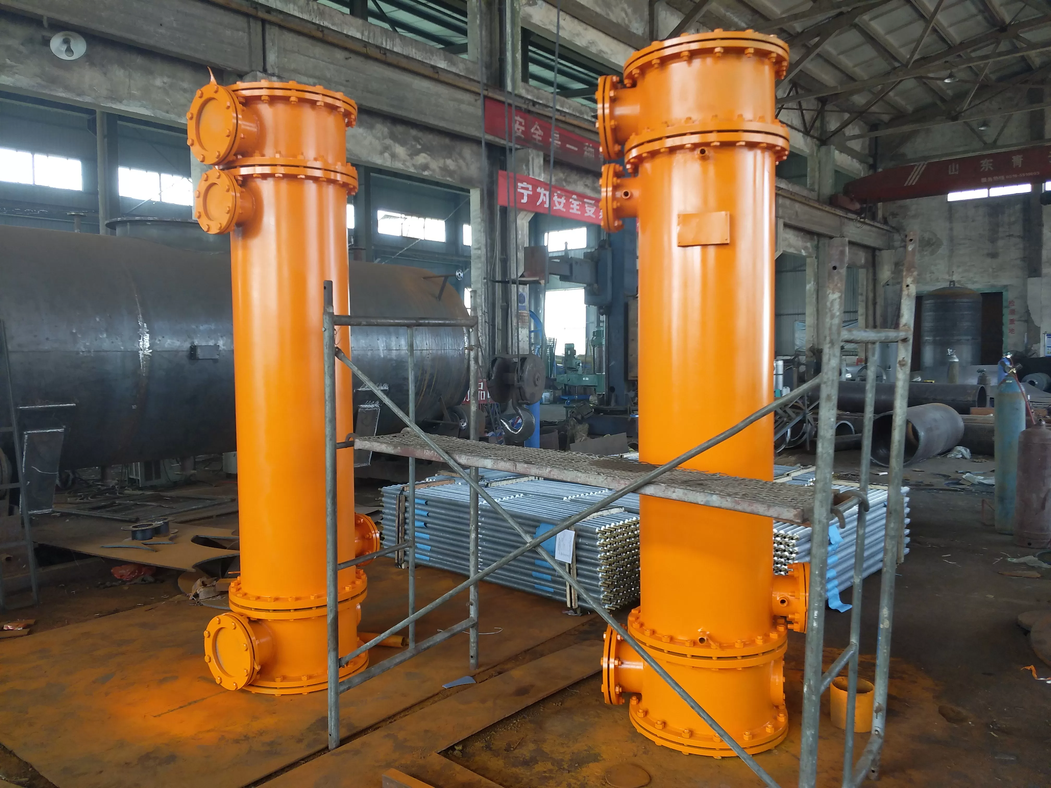
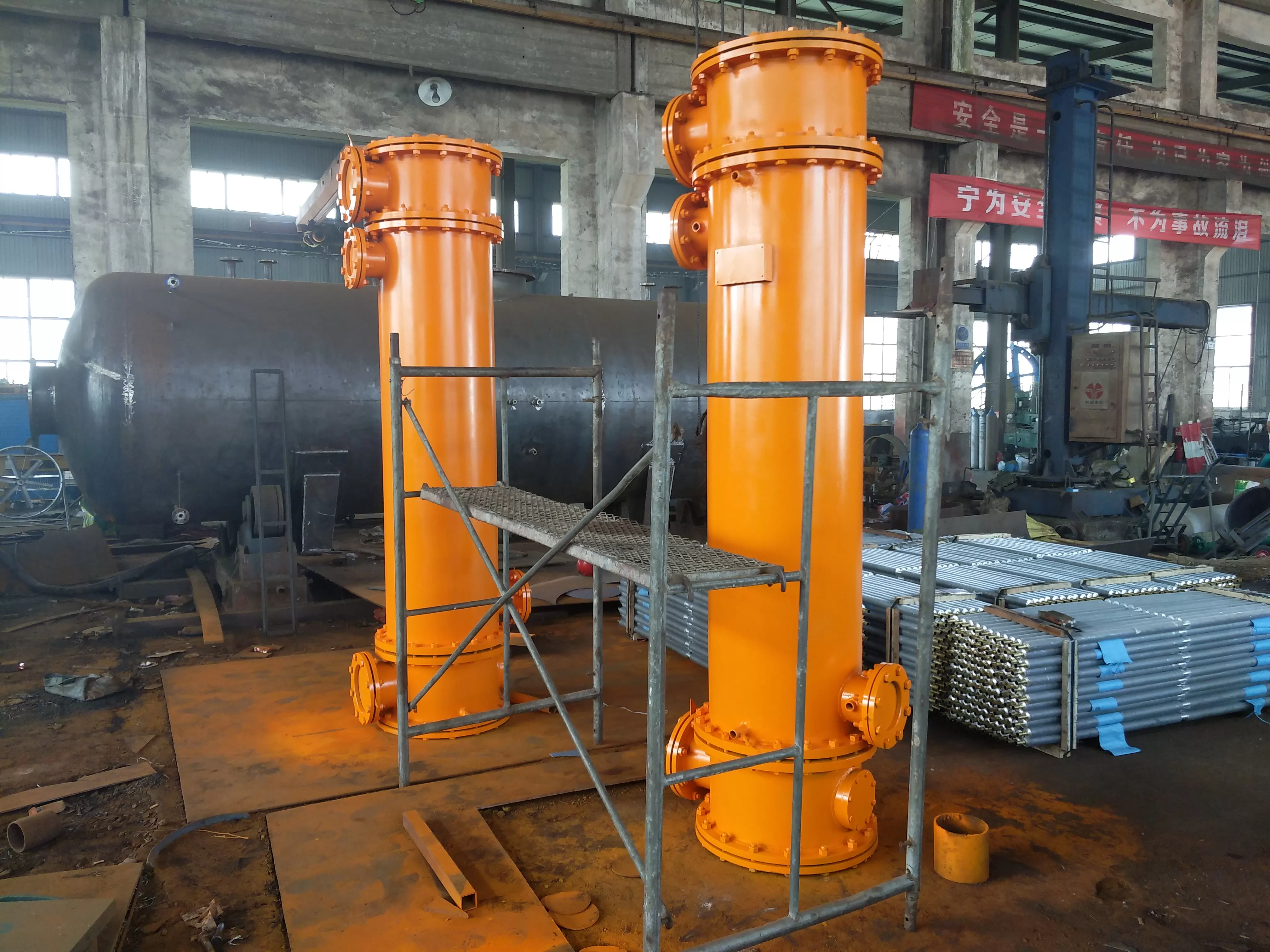
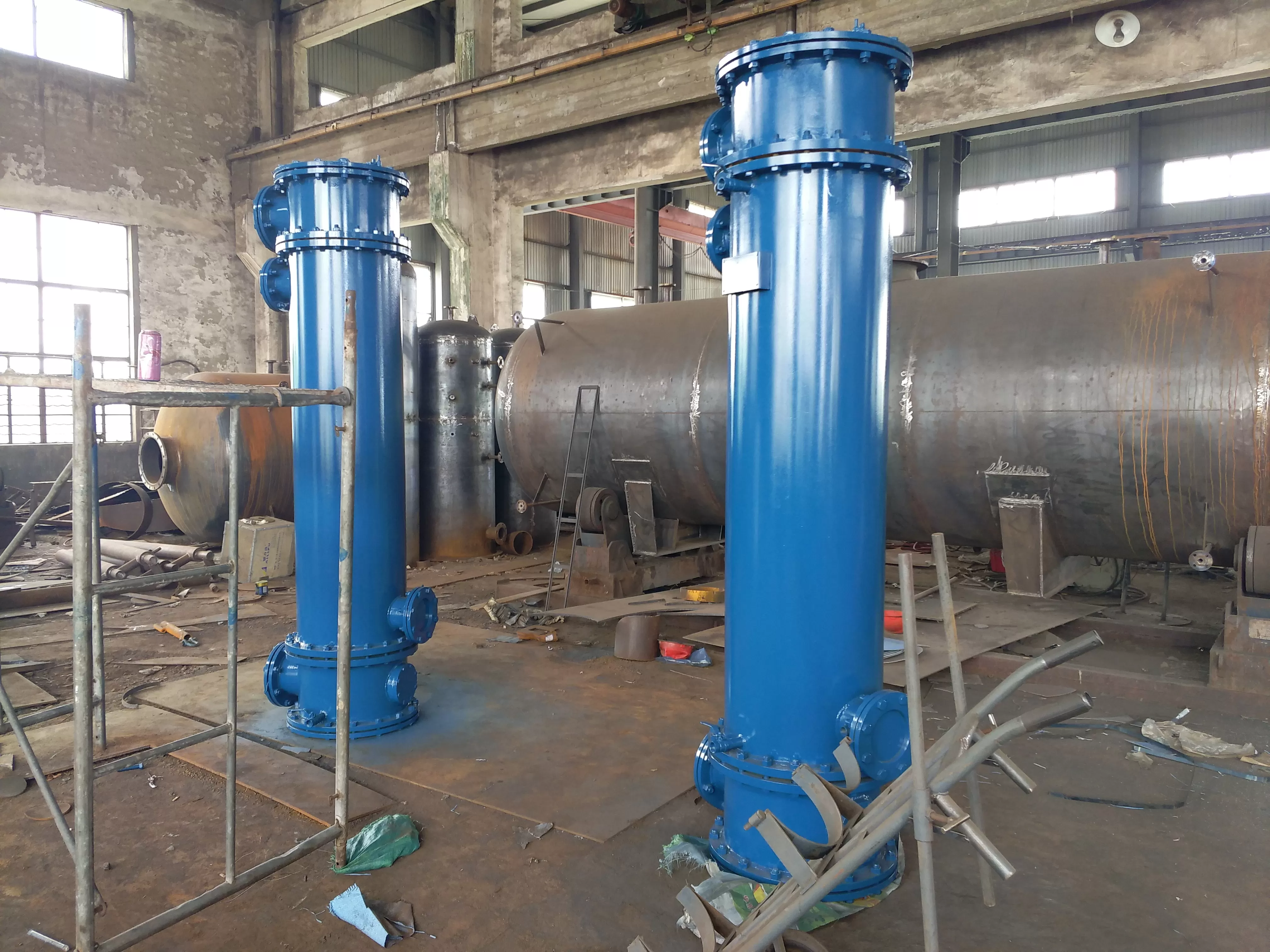
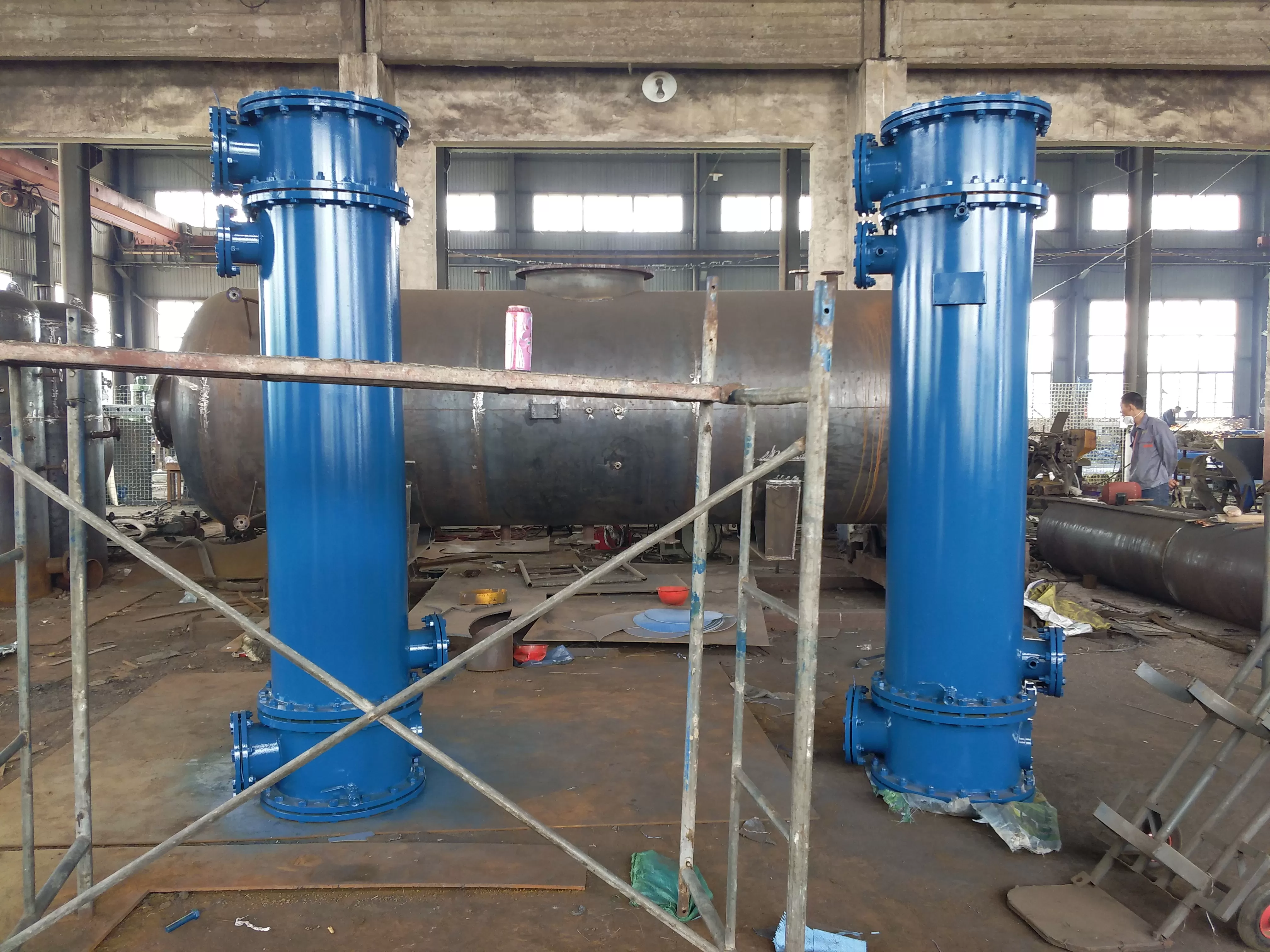
-Overview of dual oil cooler
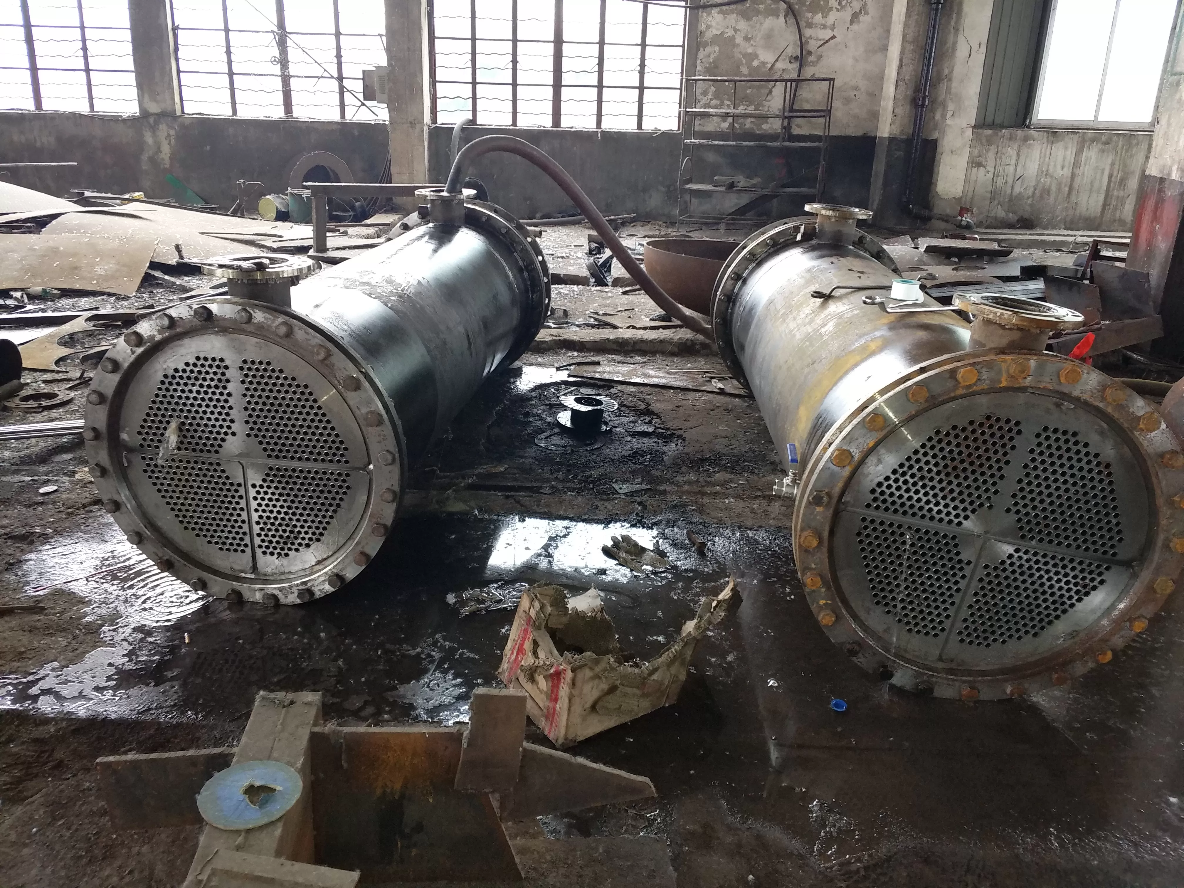
The oil cooler, which is connected in parallel, is called a dual oil cooler, and its working mode is two oil coolers in standby mode. The oil cooler is a tubular oil cooler, with horizontal or vertical connections available. The cooling area of each oil cooler can maintain the total cooling load. The dual oil cooler adopts a dual connection, consisting of two coolers with the same area and a three-way valve device, which are only in operation and only for standby. Each cooler can bear the cooling load of the entire system, with a fixed tube plate head, a floating head, a detachable tube bundle, and a water chamber cover, making it easy to clean, inspect, and maintain during operation. The material of the cooler can be selected according to the usage location and water system conditions.
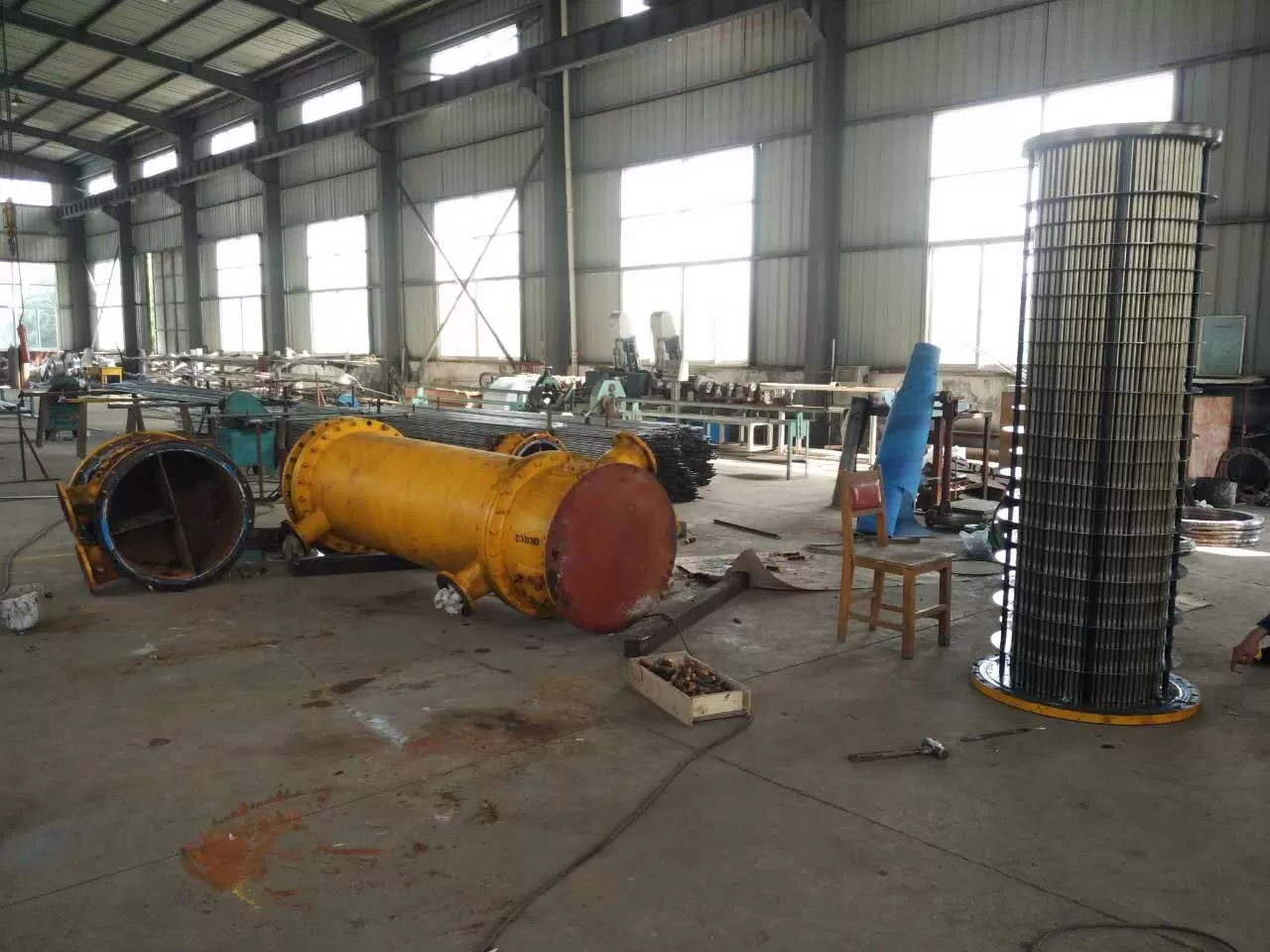
2、 Service conditions for dual oil coolers
The dual oil cooler is designed and manufactured according to the GB151 standard and referring to the AD and TEMA standards of West Germany and the United States. It is made of all steel and partial brass structure, with an oil side working pressure of 1.6 MPa, a working temperature of 150 ℃, a water side working pressure of 1.0 MPa, and a working temperature of 100 ℃. Production has energy-saving, high efficiency, safety and reliability, etc; Suitable for oil cooling systems in steam turbine generator units, compressor units, fans, pump units, and the petrochemical industry, as well as other oil cooling systems. Therefore, it is also known as the generator unit cooler, compressor unit cooler, fan oil cooler, and pump unit oil cooler.
3、 Dual oil cooler--
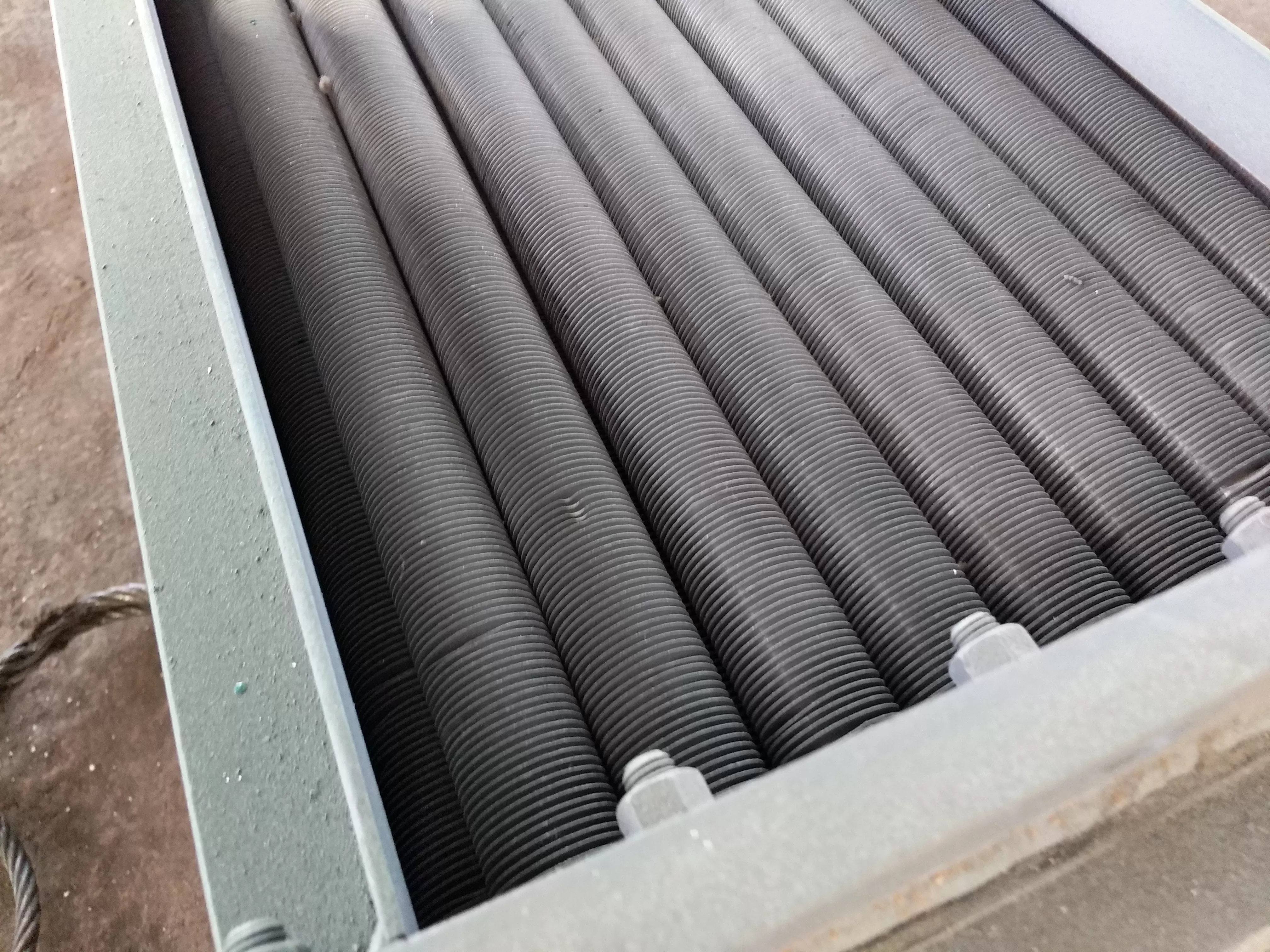
1. The data in the table is for a two process tubular double oil cooler. If necessary, a four process, six process, - tube, or finned cooling tube cooler can be selected.
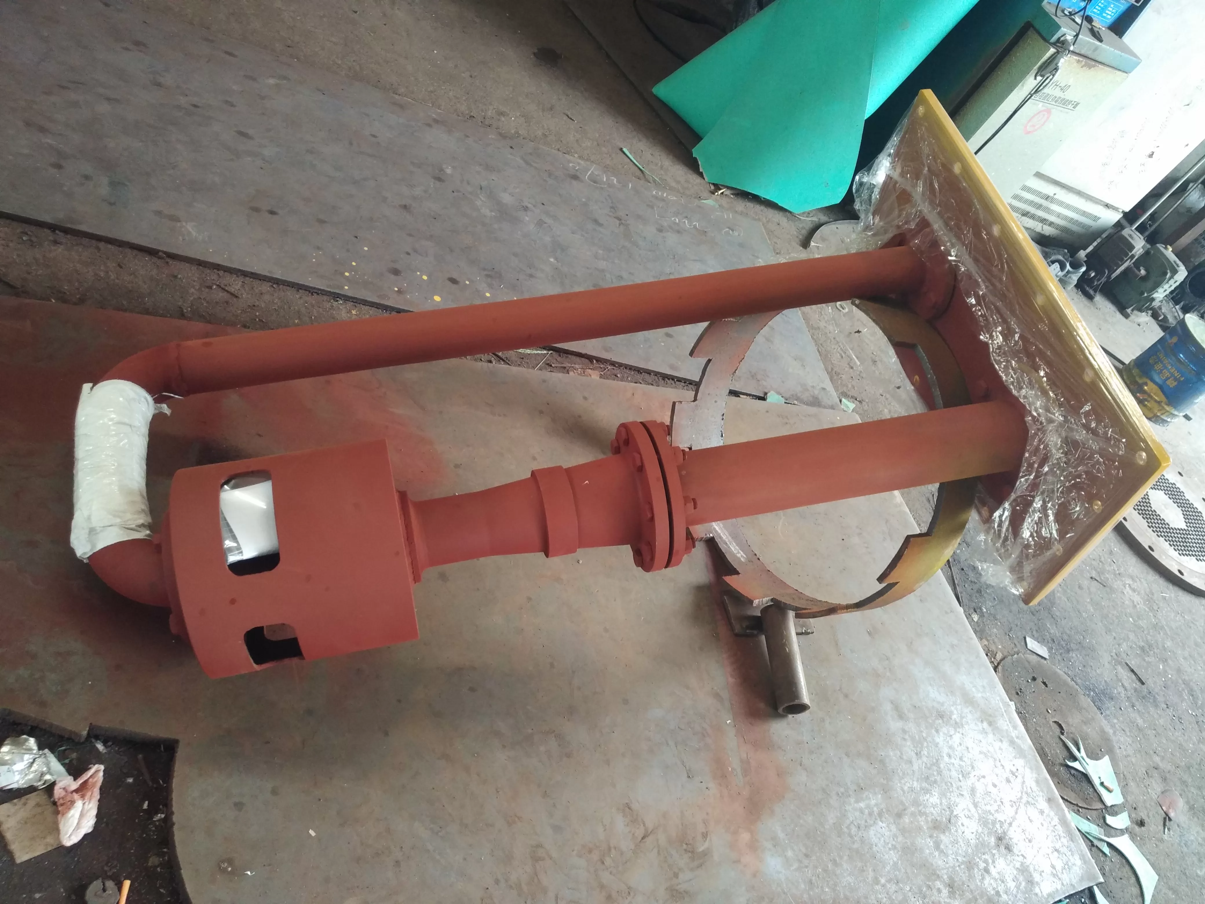
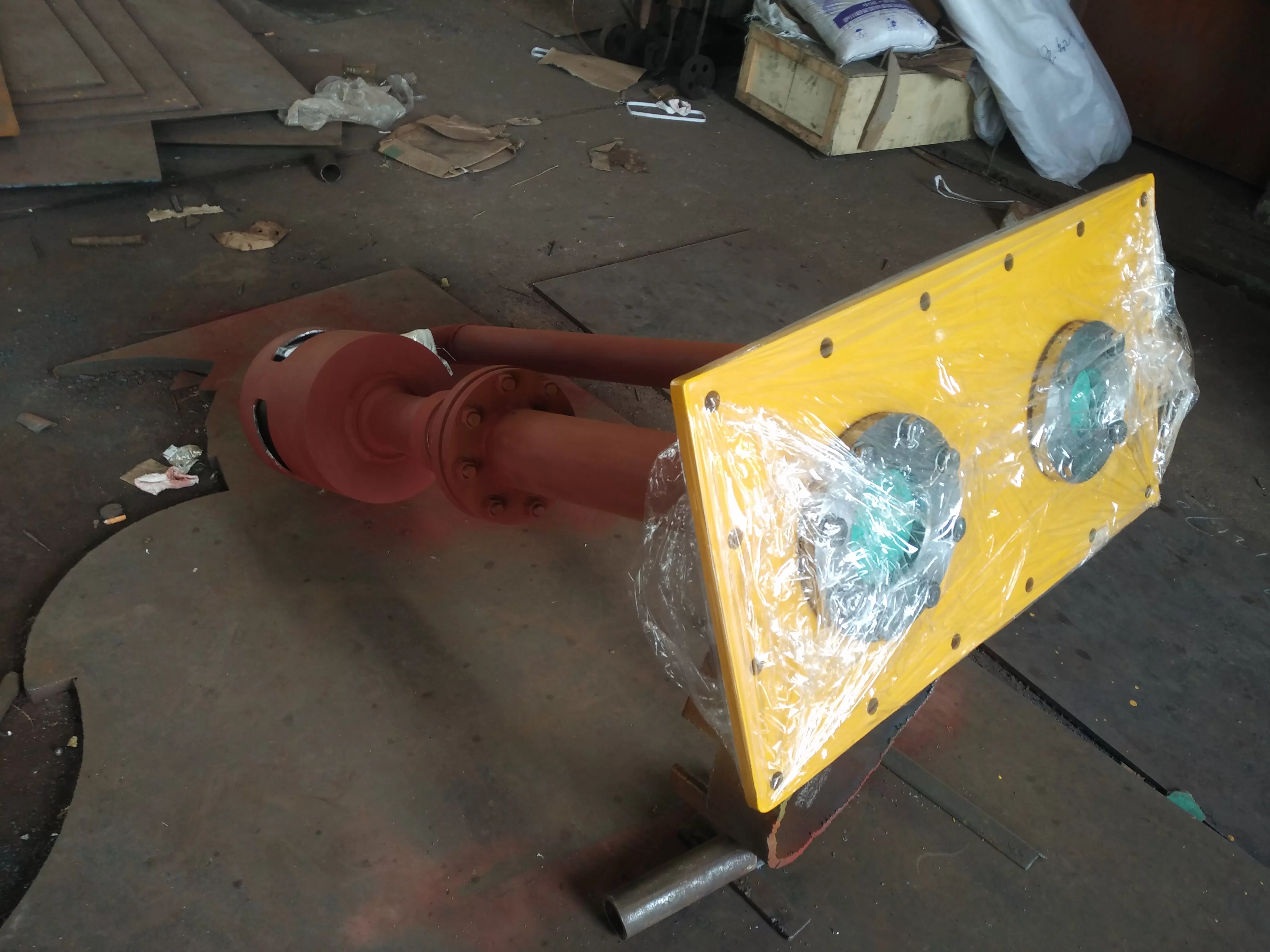
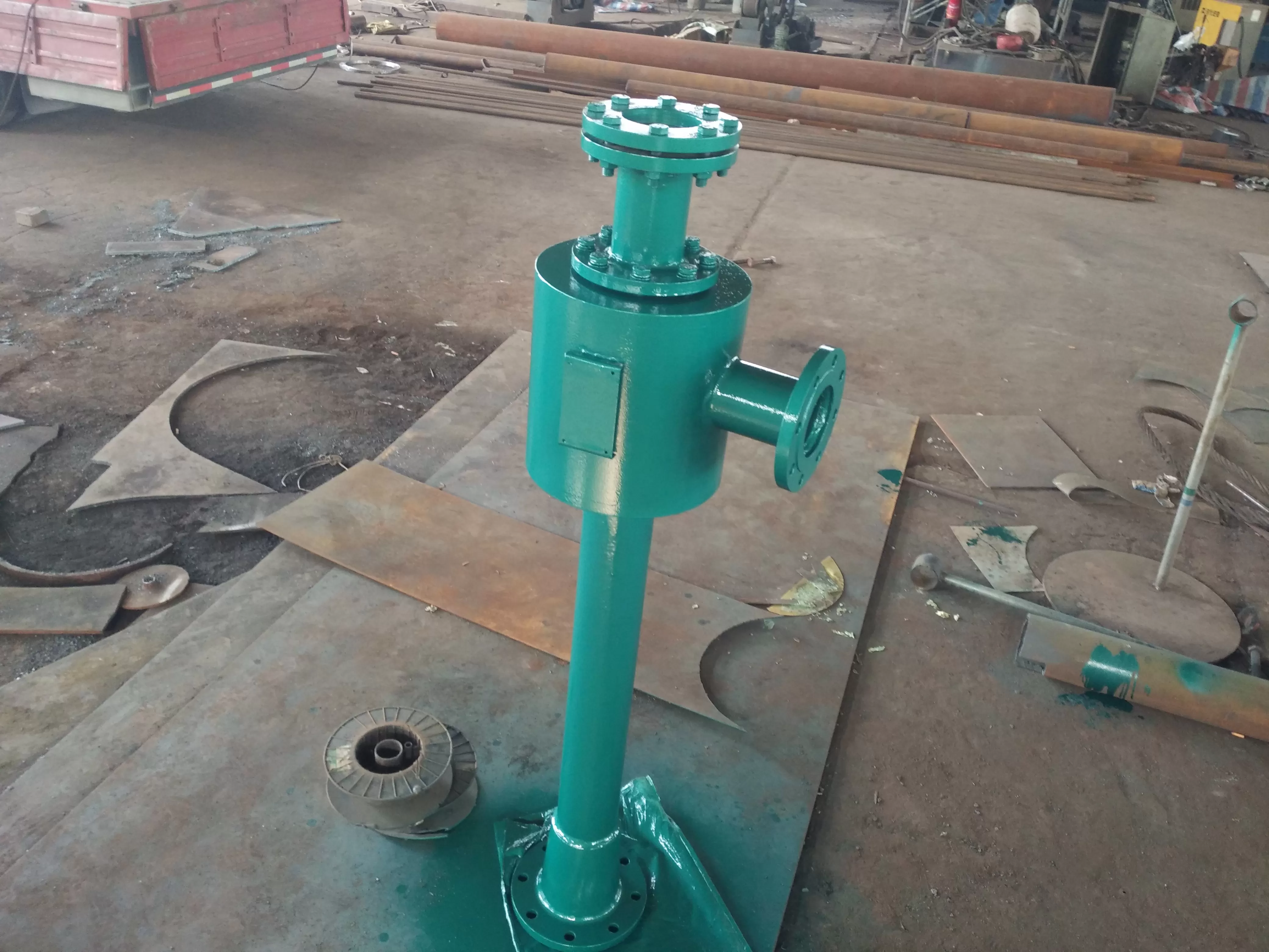
2. The installation of the cooler is generally horizontal. If the user needs it, two vertical arrangements can be adopted, one with the inlet chamber at the bottom and the other with the inlet chamber at the top, making it easy to disassemble the pipe bundle.
3. The standard for oil-water interface flanges is in accordance with JB/T81-94, and non-standard flanges should meet piping requirements when equipped according to user requirements.
4. According to the AP Ⅰ 614 standard, the cooler adopts a double connection type. The cooler is composed of two coolers with the same area and a three-way valve device, working only and standby only. Each cooler can withstand the cooling load of the entire system, with fixed tube plates and floating heads, detachable tube bundles and water chamber box covers for easy cleaning, inspection, and maintenance during operation. The material of the cooler can be selected according to the usage location and water system conditions. The water chamber, shell, and three-way valve can be made of carbon steel or all stainless steel, and the pipe plate can be made of carbon steel, stainless steel, or brass plate; The pipe materials can be ordinary brass tube H68, arsenic brass tube HSn70-1A, aluminum brass tube HA177-2A, stainless steel tubes 1Cr18Ni9Ti, B10, B30, etc.
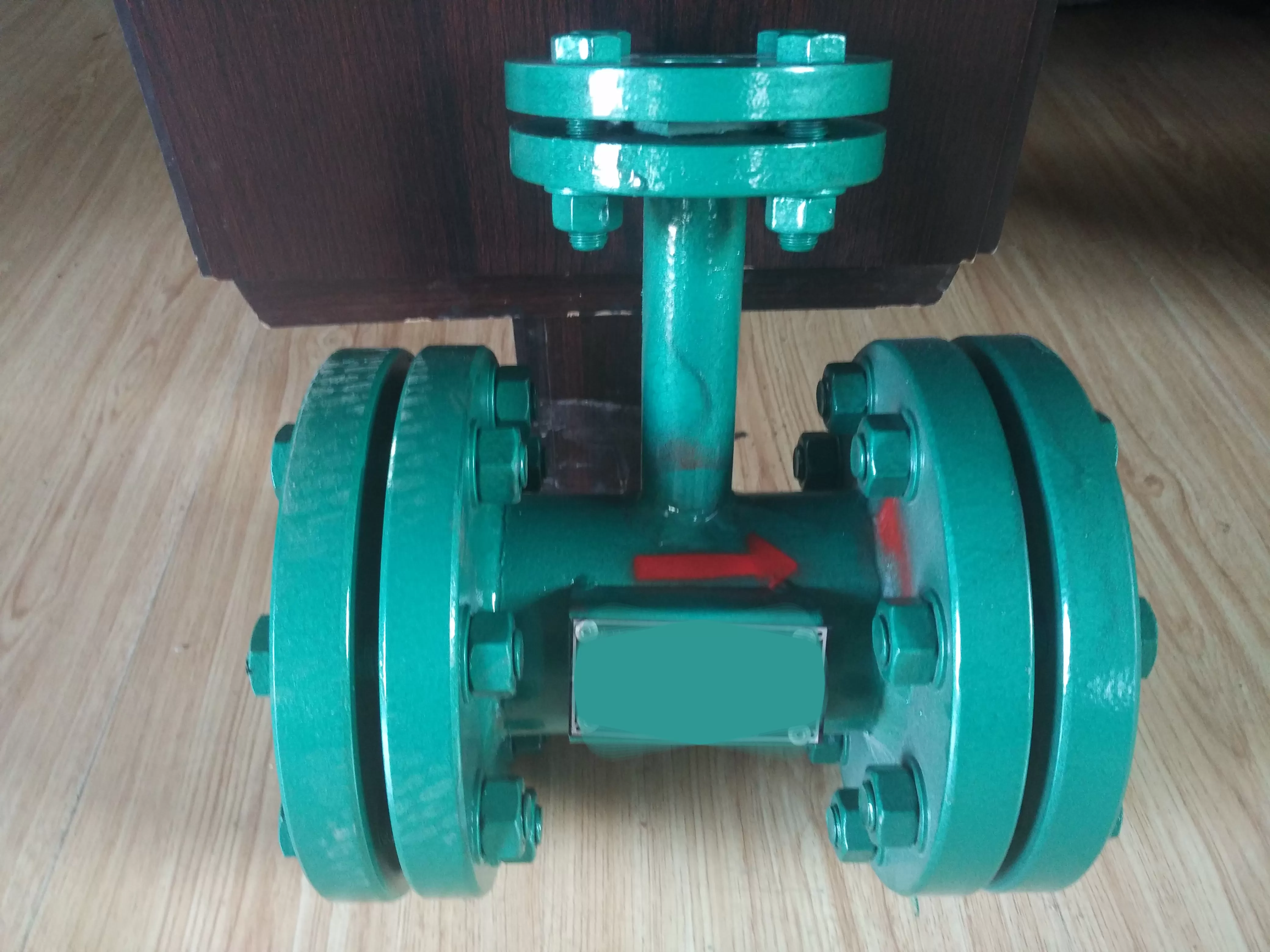
5. The three-way valve of the cooler adopts a steel welded joint continuous flow conversion valve. This type of valve will not cause oil circuit interruption during internal structural failure or valve switching.
4、 Double oil cooler junction-
The schematic diagram of the oil cooler is as follows:
View of oil cooler - description of each part number is as follows:
1. Three way switching device 2. Oil cooler 3. Water chamber exhaust port 4. Rear pipe plate
5. Compression washer 6. Sealing ring 7. Shell side exhaust port 8. Shell
9. Tube bundle 10. Tube plate 11. Water chamber 12. Water outlet
13. Rear water chamber 14. Oil inlet and outlet 15 Oil drain port
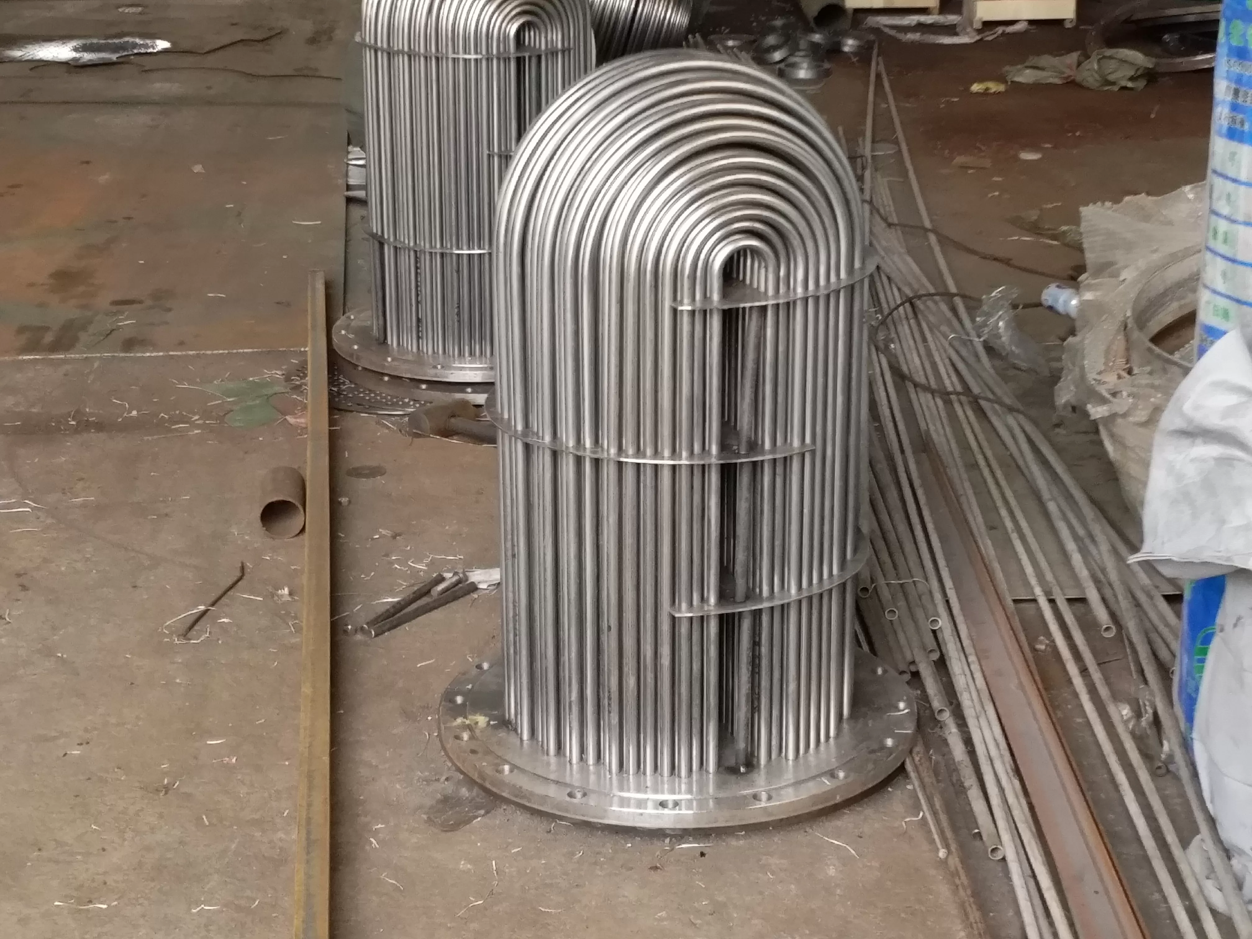
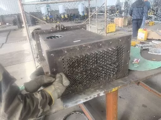
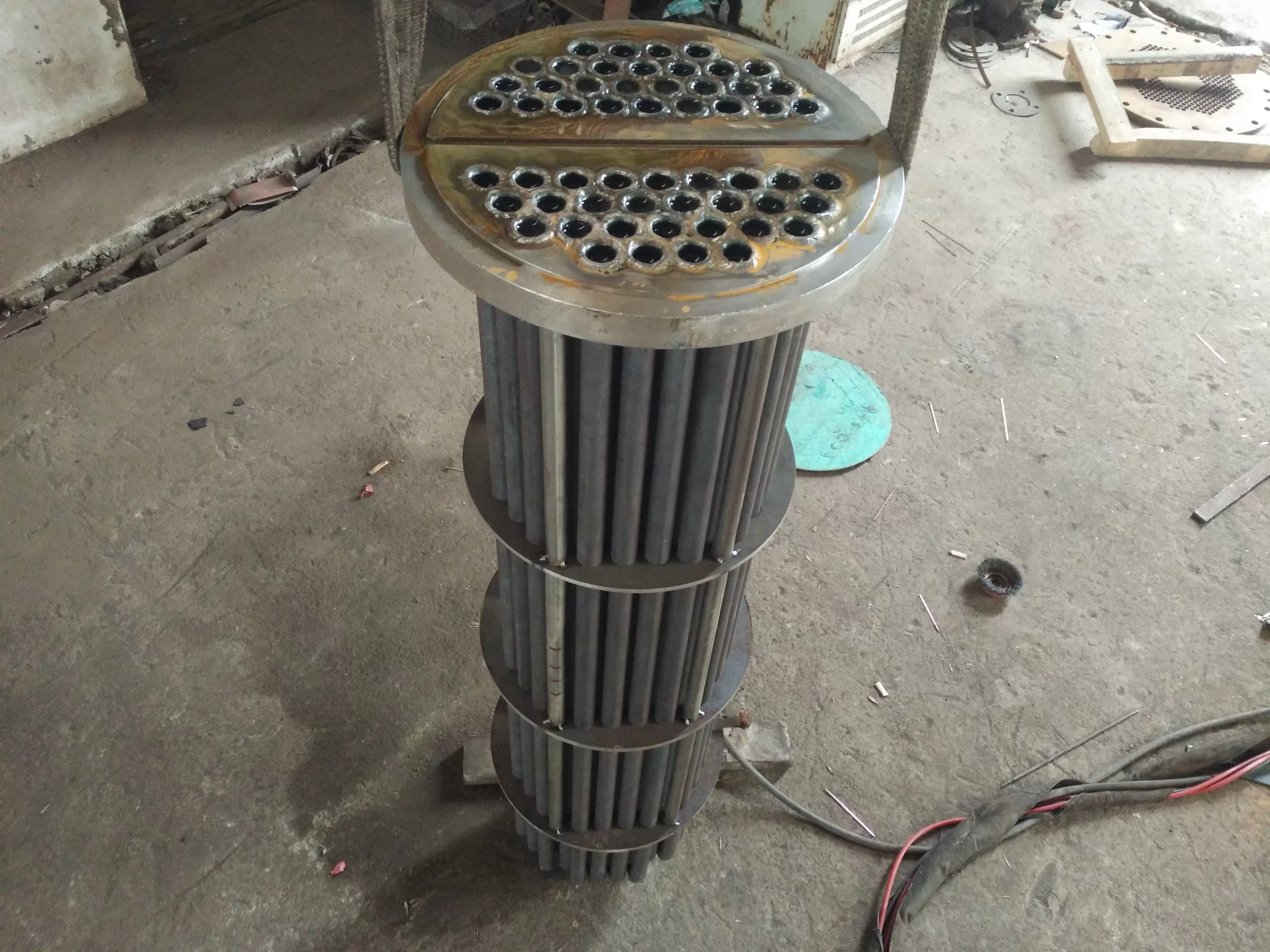
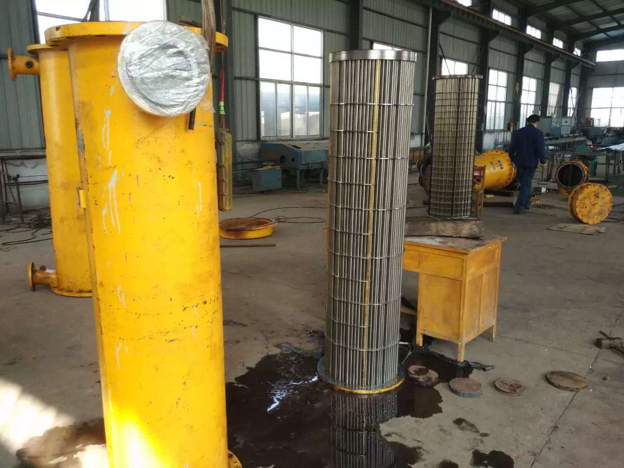
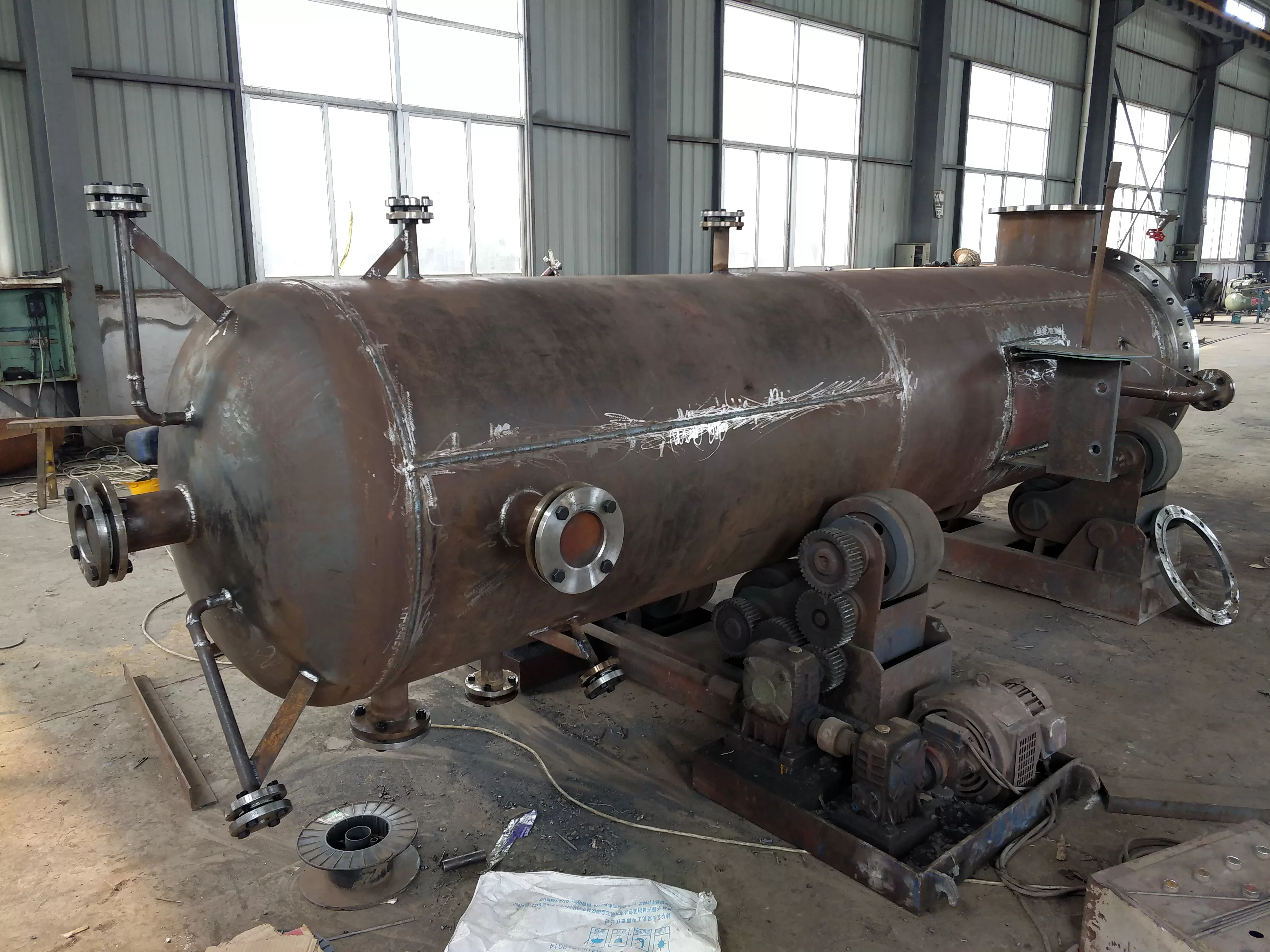
The oil cooler mainly consists of the oil cooler housing, tube bundle, water chamber, and rear water chamber.
The shell of the oil cooler adopts a welded joint, and there are oil and gas discharge ports, oil discharge ports, and oil inlet and outlet ports on the shell.
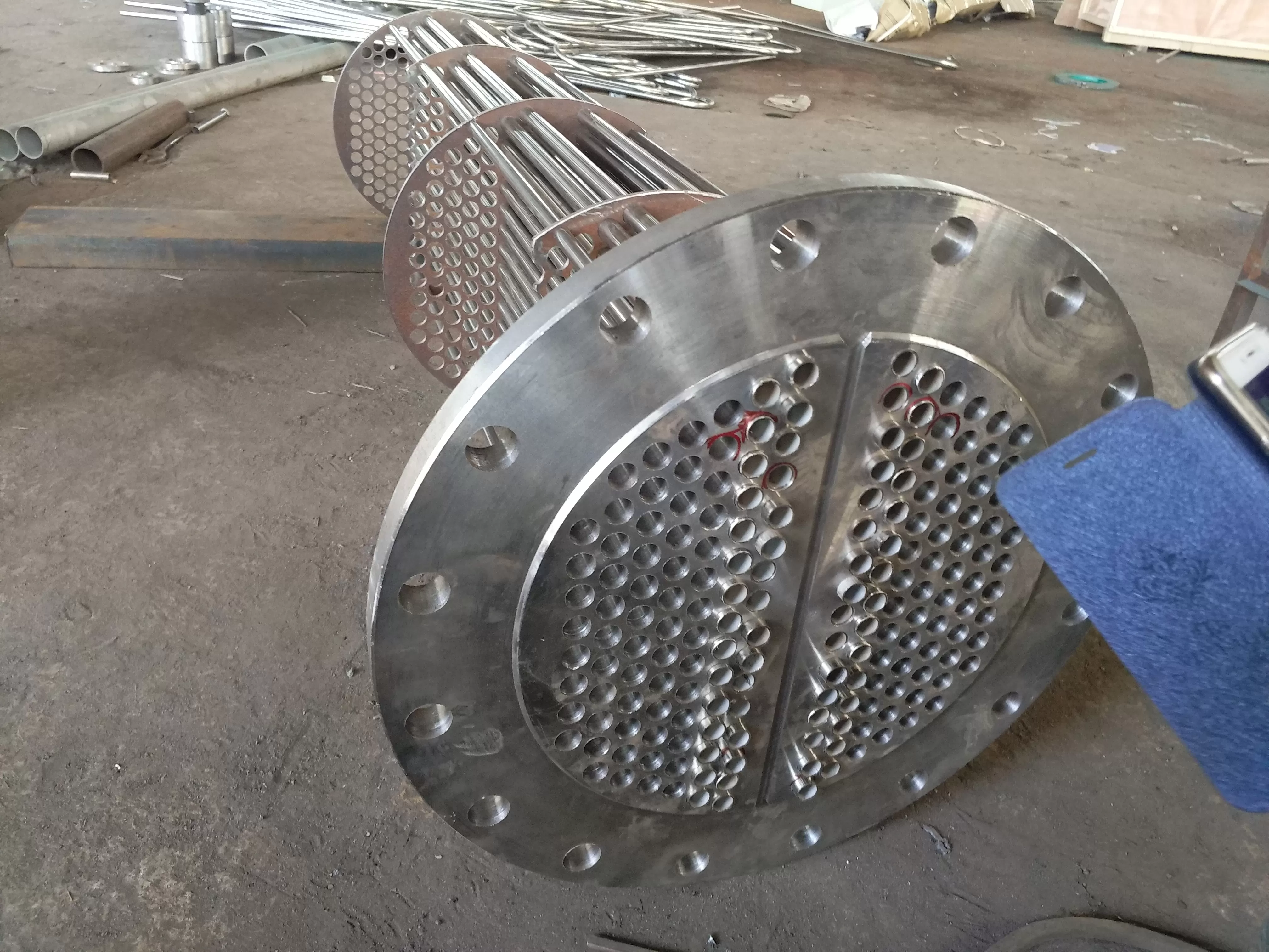
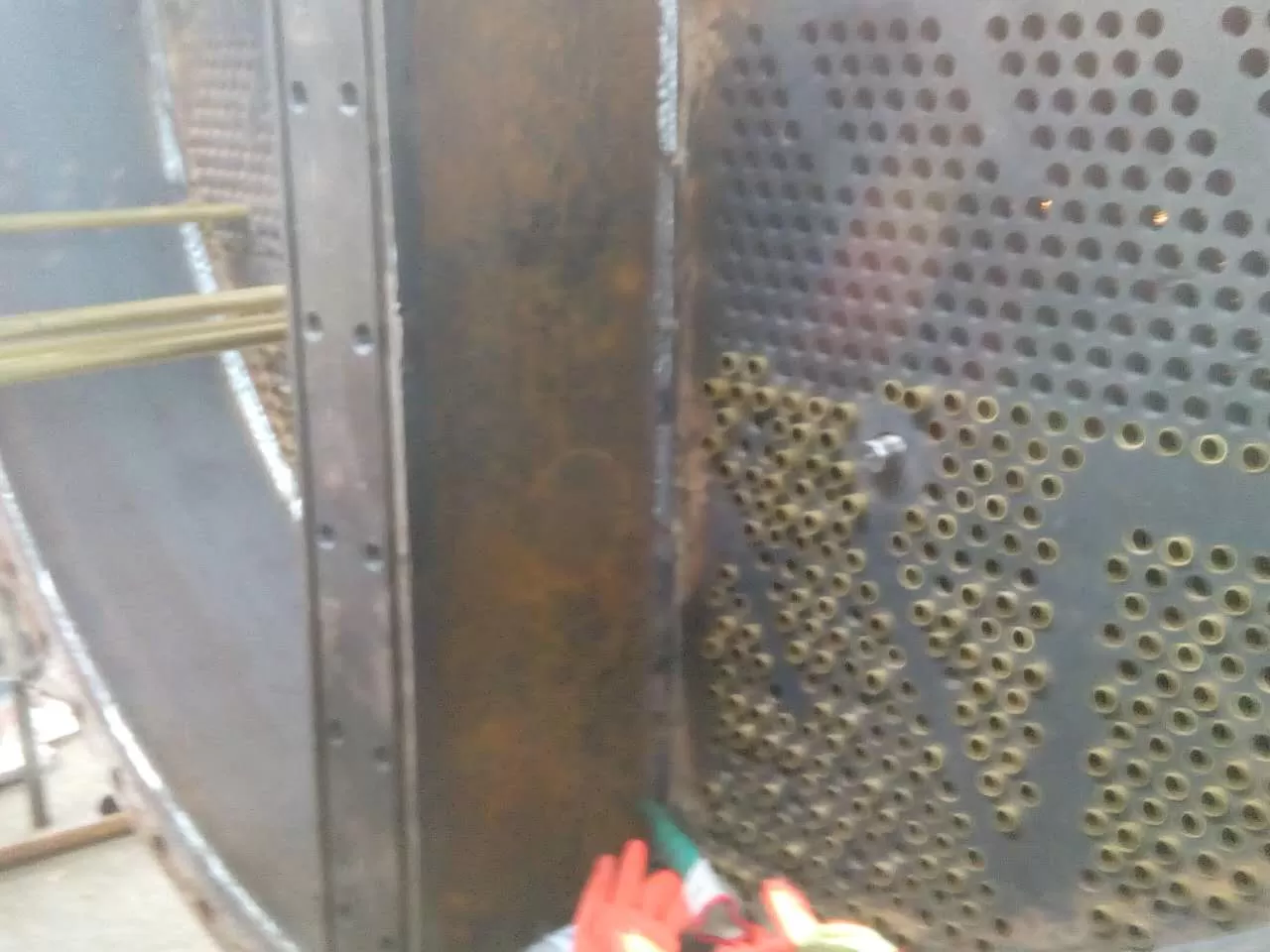
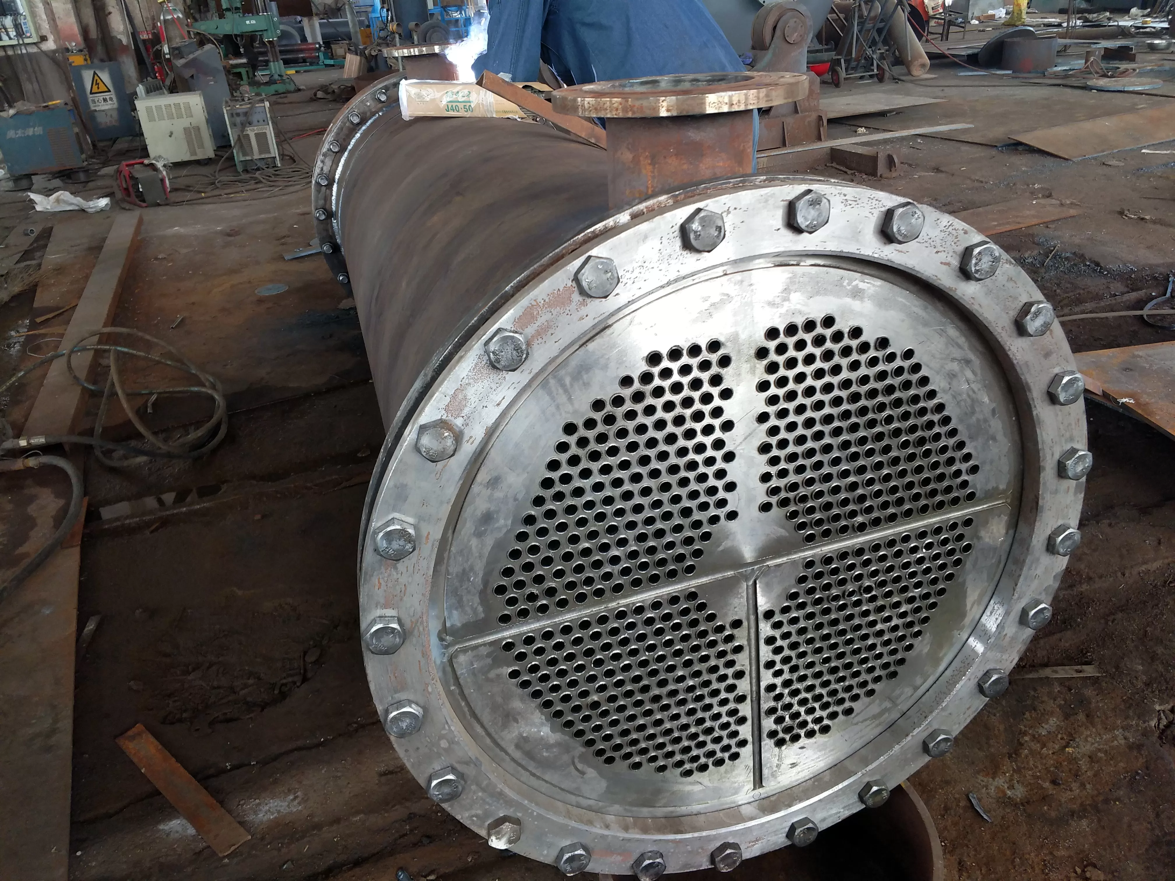
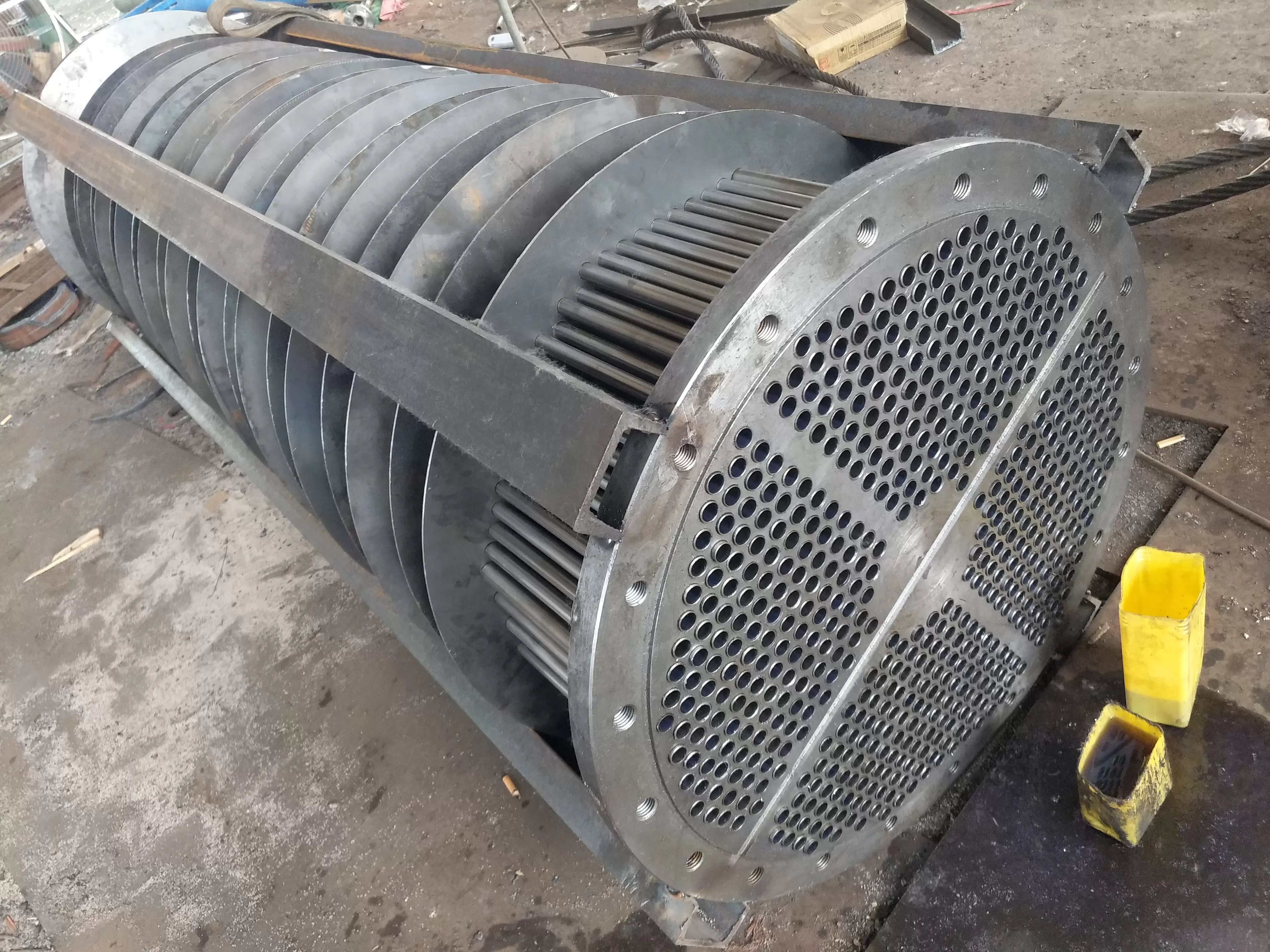
The tube bundle consists of tubes, tube plates, partitions, spacing tubes, tensioning bolts, etc. The tube and tube plate are connected by expanding the tube, and the partition is fixed by a fixed distance tube and tension bolts.
-The rear water chamber adopts a welded joint, and there are exhaust and drainage ports on the rear water chamber. The water chamber is connected to the inlet and outlet pipes. The water chamber design adopts a two flow path structure.
-The tube plate and the shell are fixed, while the rear tube plate is floating. The sealing design of the rear tube plate adopts a sealing structure composed of a pressure washer between flanges and several oil rubber sealing rings.
Water flows inside the pipe, while oil flows outside the pipe. Hot oil enters the oil cooler through the oil inlet (which can be switched) and changes the direction of oil flow through a baffle, resulting in a longer oil flow path and sufficient heat exchange between the oil and the water inside the pipe. When the oil comes out of the oil outlet, it becomes cold oil that meets the required temperature.
5、 The use of dual oil coolers
Rotate the operating linkage of the three-way switching device so that the oil flow indicator on the three-way switching device points towards a certain oil cooler.
Observe the oil flow indicator on the three-way switching device and identify the oil cooler that needs to be used.
Open the air outlet on the oil cooler that needs to be used and the vent valve on the pipeline connecting the oil tank.
Open the air release valve on the water chamber after the oil cooler, and then slowly open the inlet valve of the oil cooler (with the discharge valve closed). When water overflows, close the inlet valve and also close the vent valve.
After the oil pump is turned on, observe the sight glass on the oil cooler's oil discharge port and the oil tank connection pipeline. When all the oil flows out, it indicates that the oil cooler housing is filled with oil, and close the air release valve. At this point, both water and oil are in a static state, and after heat exchange, the temperature difference gradually decreases.
After the water temperature rises by 5-8 ℃, open the cooling water discharge valve and gradually open the cooling water inlet valve to allow water to flow; At the same time, open the oil outlet valve to make the oil flow, and then adjust the water volume of the oil cooler to maintain the oil outlet temperature at a positive state of -.
When the oil cooler is first used, it is important to avoid opening the inlet valve too quickly to prevent a poor thermal conductivity layer on the surface of the heat exchange tube due to the large amount of cooling water flowing in. Otherwise, even if a large amount of water enters, the presence of the "supercooled layer" will seriously affect the heat transfer results.
The oil cooler has been put into use.
When starting up, fill with water and then oil; When shutting down - turn off the oil and then turn off the water, and drain the water completely.
6、 Switching of dual oil coolers
If the cooling water volume of the oil cooler does not change and the inlet water temperature is positive, and the outlet oil temperature of the oil cooler is greater than 48 ℃, it indicates that the oil cooler is contaminated;
When inspecting water and oil, the oil cooler may be used for oil;
At this point, the dual oil cooler should be switched and a backup oil cooler should be used. Just put into operation and normal operation, avoid frequent switching.
Switching operation sequence of dual oil cooler:
1. Observe the oil flow indicator on the three-way switching device and clarify the backup oil cooler.
2. Open the exhaust connector on the backup oil cooler and the vent valve on the fuel tank connection pipeline.
3. Open the pressure balance valve on the three-way switching device again. Fill the spare oil cooler housing with oil.
4. Observe the sight glass on the exhaust joint and oil tank connection pipeline of the standby oil cooler. When all oil flows out, it indicates that the housing of the standby oil cooler is filled with oil. Close the air release valve.
5. Open the cooling water inlet and outlet valves of the standby oil cooler to put it into use.
6. Rotate the handle of the three-way switching device and observe the oil flow indicator of the three-way switching valve to put the standby oil cooler into use.
7. Close the pressure balancing valve.
8. Close the inlet and outlet valves of the replaced oil cooler for cooling water, and drain any accumulated water inside the oil cooler.
When not using the oil cooler in cold seasons, it is necessary to drain all remaining oil and water in the oil cooler to prevent freezing and cracking.
7、 Diagram of model rules for horizontal dual oil coolers
Diagram of model rules for horizontal dual oil coolers
8、 Parameter table for horizontal dual oil cooler
| 型号 | 冷却面积m2 | DN1 | DN2 | D1 | L | L3 | C | H2 | e | L2 | C1 | C2 | B | H | H1 |
| SGLL4-12/1.0 | 12 | 65 | 65 | 325 | 1555 | 660 | 860 | 262 | 870 | 497 | 345 | 300 | 370 | 984 | 460 |
| SGLL4-16/1.0 | 16 | 65 | 65 | 325 | 1960 | 1065 | 1365 | 262 | 870 | 497 | 345 | 300 | 370 | 98 | 460 |
| SGLL4-20/1.0 | 20 | 80 | 65 | 325 | 2370 | 1475 | 1775 | 262 | 870 | 497 | 345 | 300 | 370 | 1004 | 480 |
| SGLL4-24/1.0 | 24 | 80 | 65 | 325 | 2780 | 1885 | 2175 | 262 | 870 | 497 | 350 | 300 | 370 | 1004 | 480 |
| SGLL4-28/1.0 | 28 | 80 | 65 | 325 | 3190 | 2295 | 2585 | 262 | 870 | 497 | 350 | 300 | 370 | 1004 | 480 |
| SGLL4-35/1.0 | 35 | 100 | 100 | 426 | 2480 | 1232 | 1692 | 313 | 890 | 730 | 500 | 300 | 730 | 1181 | 555 |
| SGLL5-40/1.0 | 40 | 100 | 100 | 426 | 2750 | 1502 | 1962 | 313 | 890 | 730 | 500 | 300 | 730 | 1181 | 555 |
| SGLL5-45/1.0 | 45 | 125 | 100 | 426 | 3020 | 1772 | 2202 | 313 | 890 | 725 | 515 | 300 | 725 | 1181 | 585 |
| SGLL5-50/1.0 | 50 | 125 | 100 | 426 | 3290 | 2042 | 2472 | 313 | 976 | 725 | 515 | 300 | 725 | 1181 | 585 |
| SGLL5-60/1.0 | 60 | 125 | 100 | 426 | 3830 | 2582 | 3012 | 313 | 976 | 725 | 515 | 300 | 725 | 1181 | 585 |
| SGLL6-80/1.0 | 80 | 200 | 200 | 616 | 3160 | 1555 | 2015 | 434 | 1100 | 935 | 700 | 750 | 935 | 1688 | 820 |
| SGLL6-100/1.0 | 100 | 200 | 200 | 616 | 3760 | 2155 | 2615 | 434 | 1240 | 935 | 700 | 750 | 935 | 1688 | 820 |
| SGLL6-120/1.0 | 120 | 200 | 200 | 616 | 4360 | 2755 | 3215 | 434 | 1240 | 935 | 700 | 750 | 935 | 1688 | 820 |
Nine, the following parameters must
The heat exchange area-less?
Cooling tube material, stainless steel, copper tube, titanium pipe, etc.?
The form of heat exchanges: -In the form of garden pipes, you can also use the form of a tube.
Specifies?
Installation form: bedroom or vertical formula?
For manufacturers who are not very clear in the cooling pipe, please provide the chlorine ion content of water quality-less, so that we can help you choose the material of the appropriate cooling pipe.