Purpose of oil cooler:
LY type oil cooler is a commonly used oil cooling equipment in the power system. By using this equipment, two liquid media with a fixed temperature difference can exchange heat, thereby reducing oil temperature and ensuring the normal operation of power equipment. It is mainly used for lubricating oil cooling, variable speed oil cooling, transformer oil cooling, and oil circulation cooling of steam turbines and coal mills.
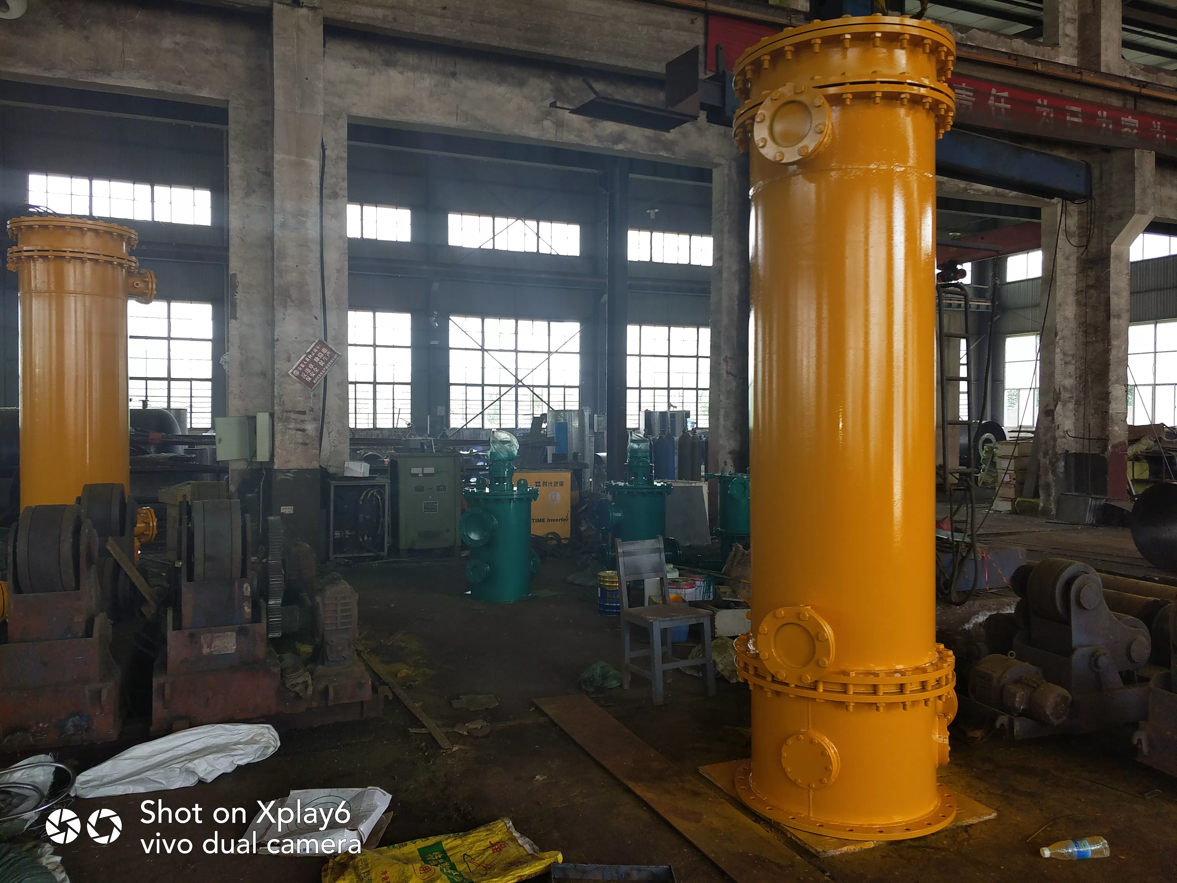
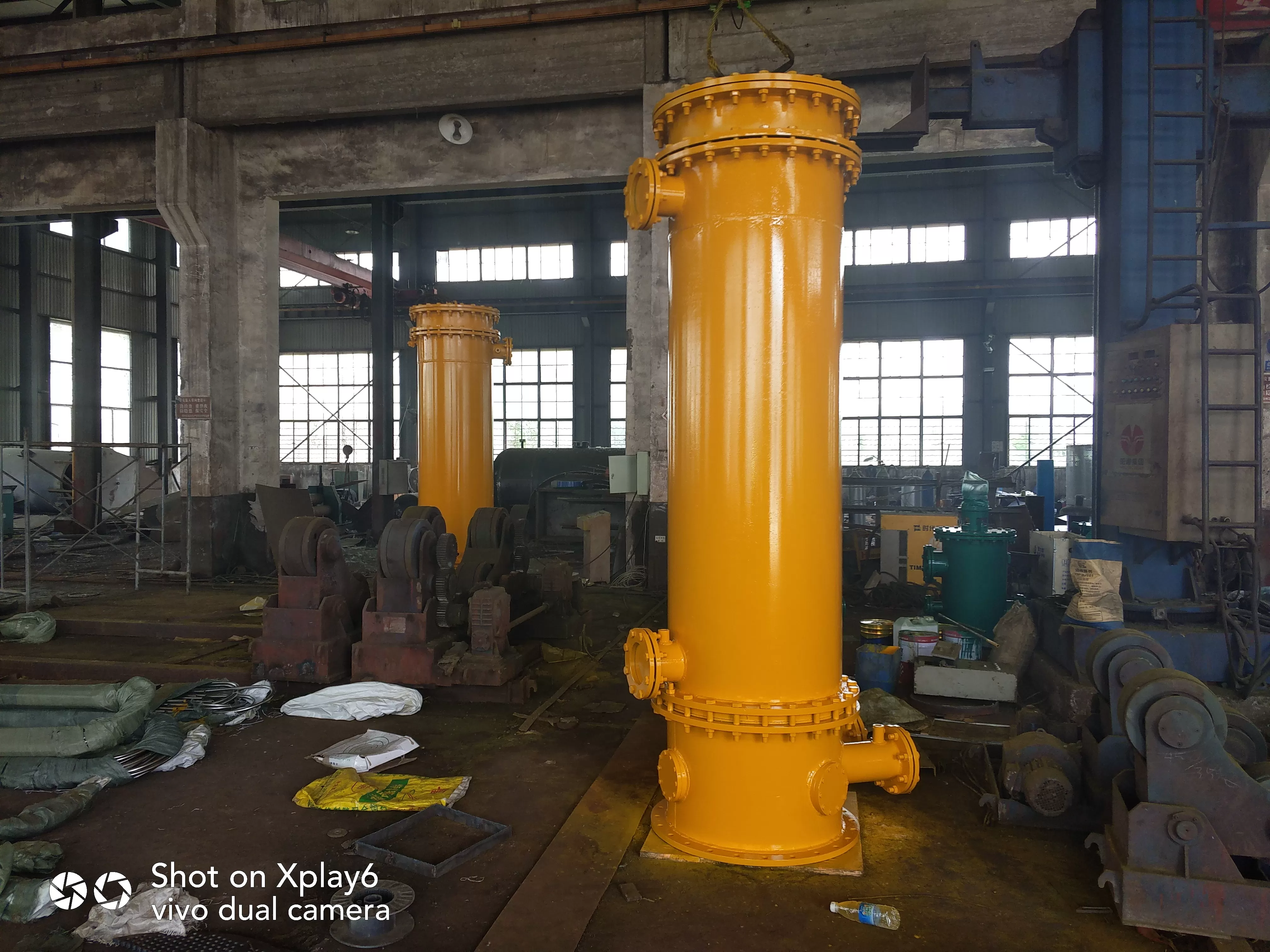
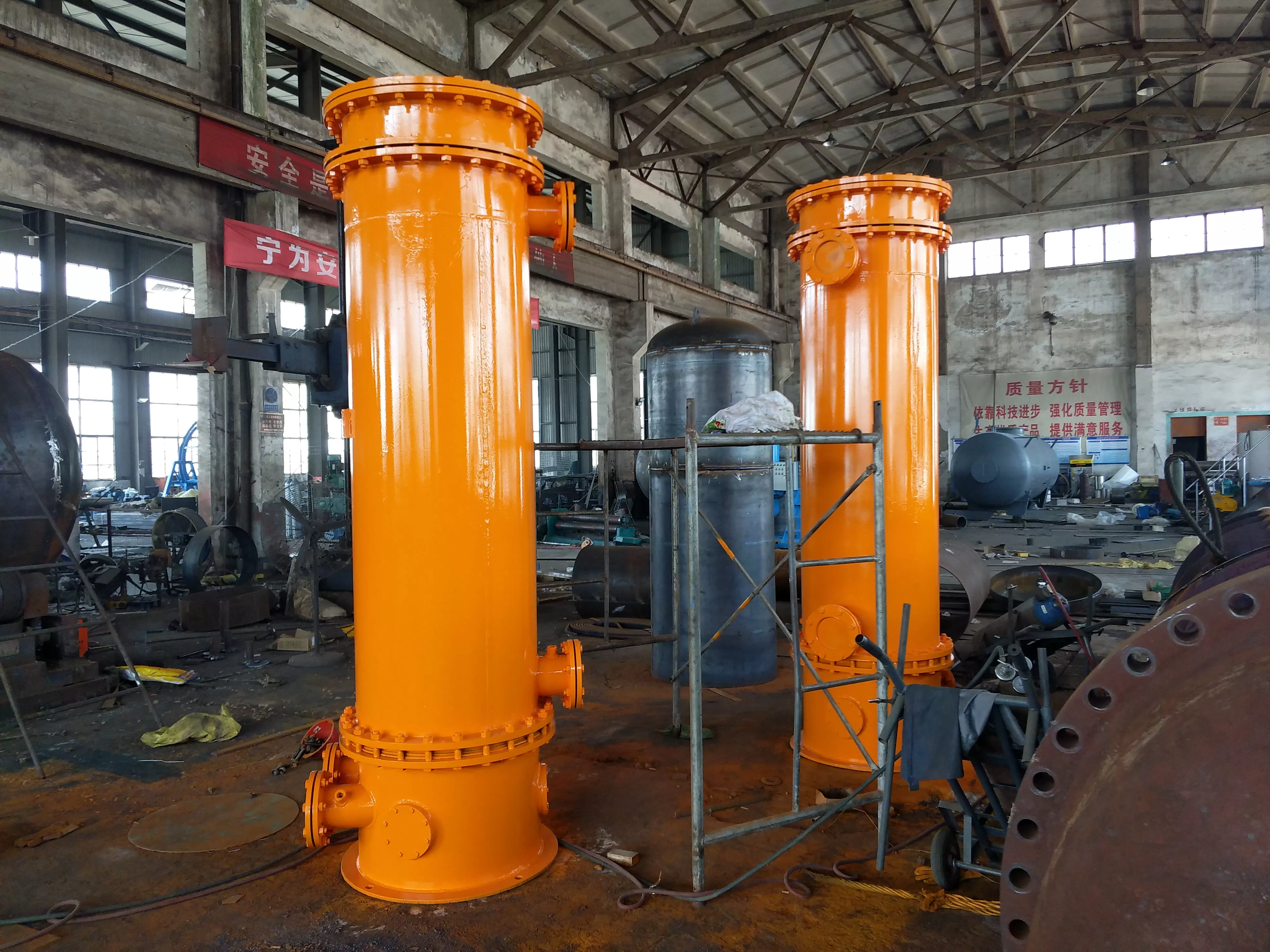
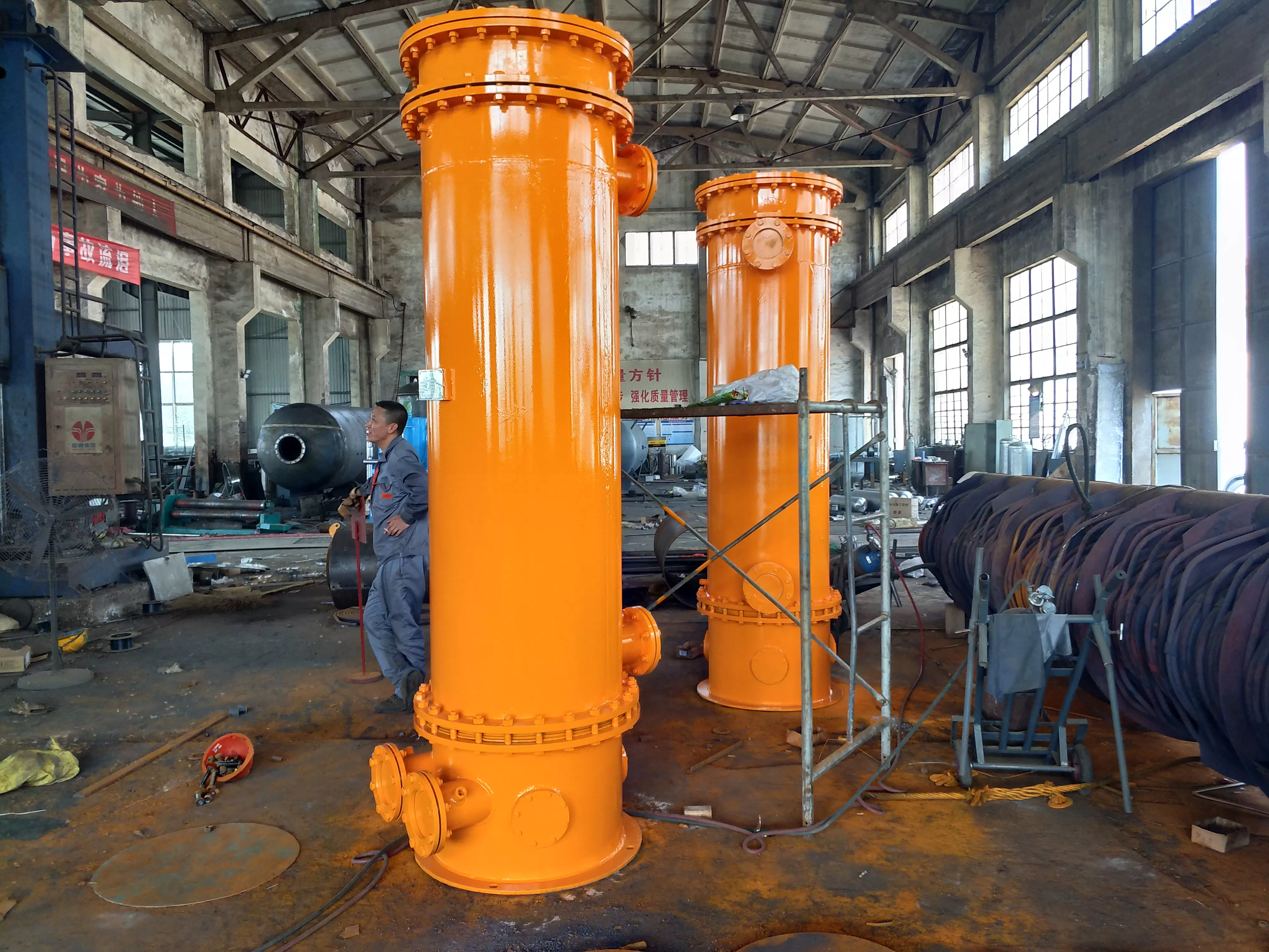
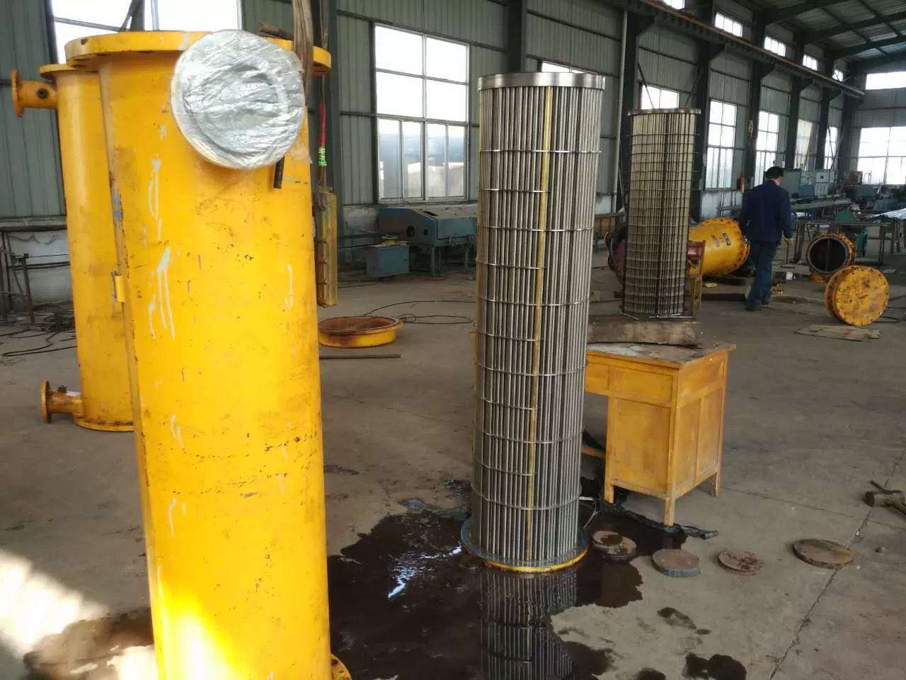
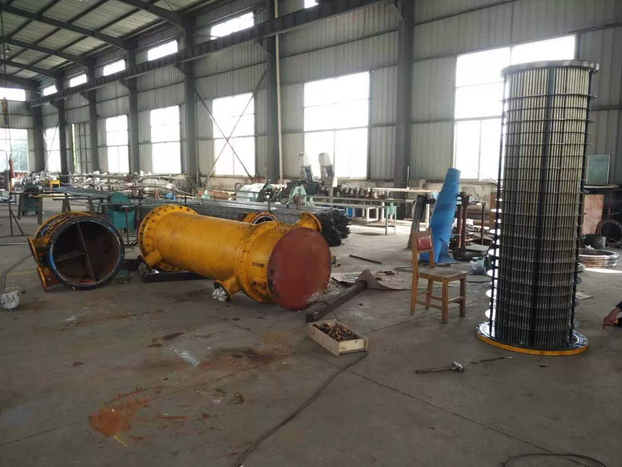
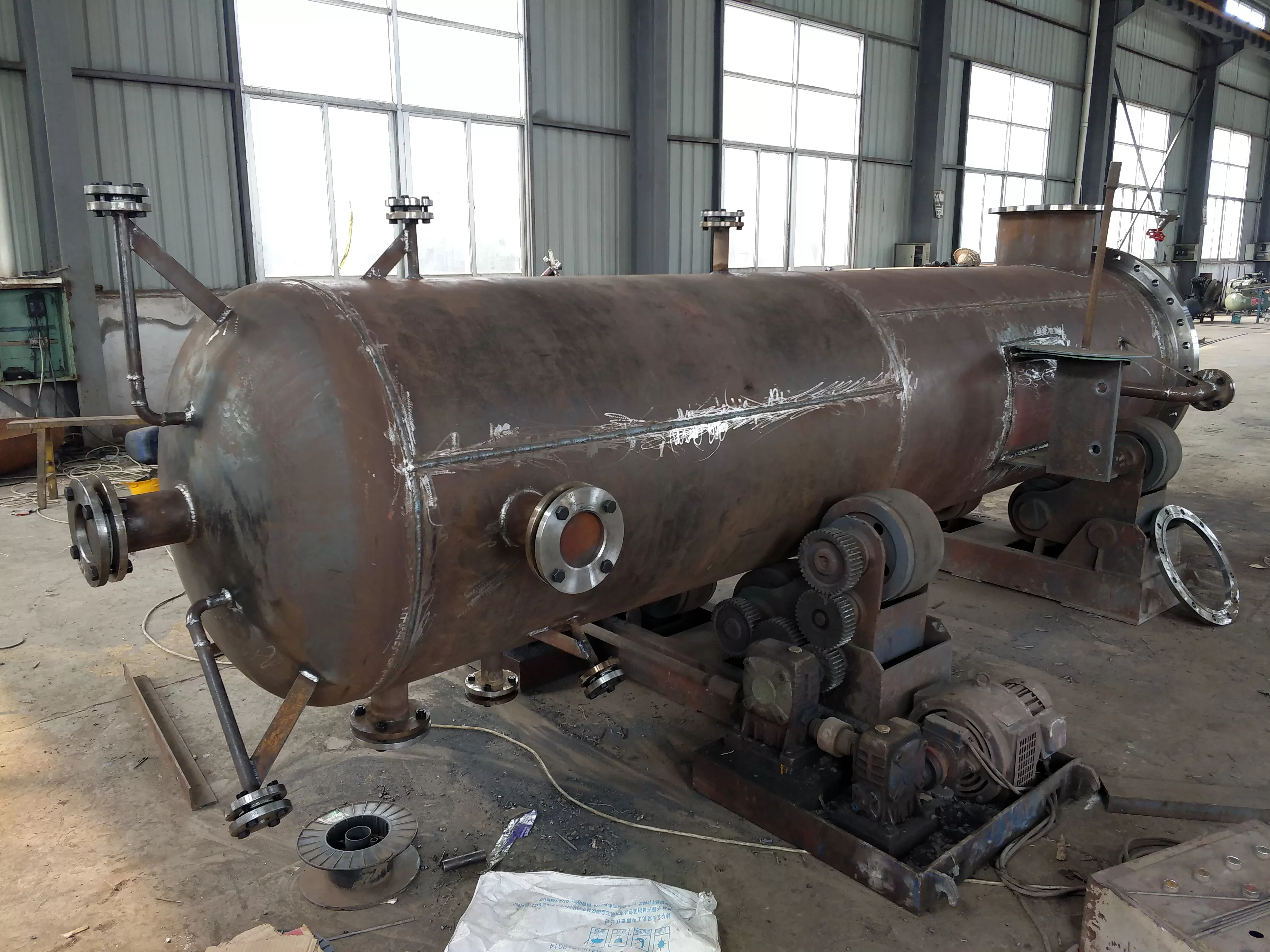
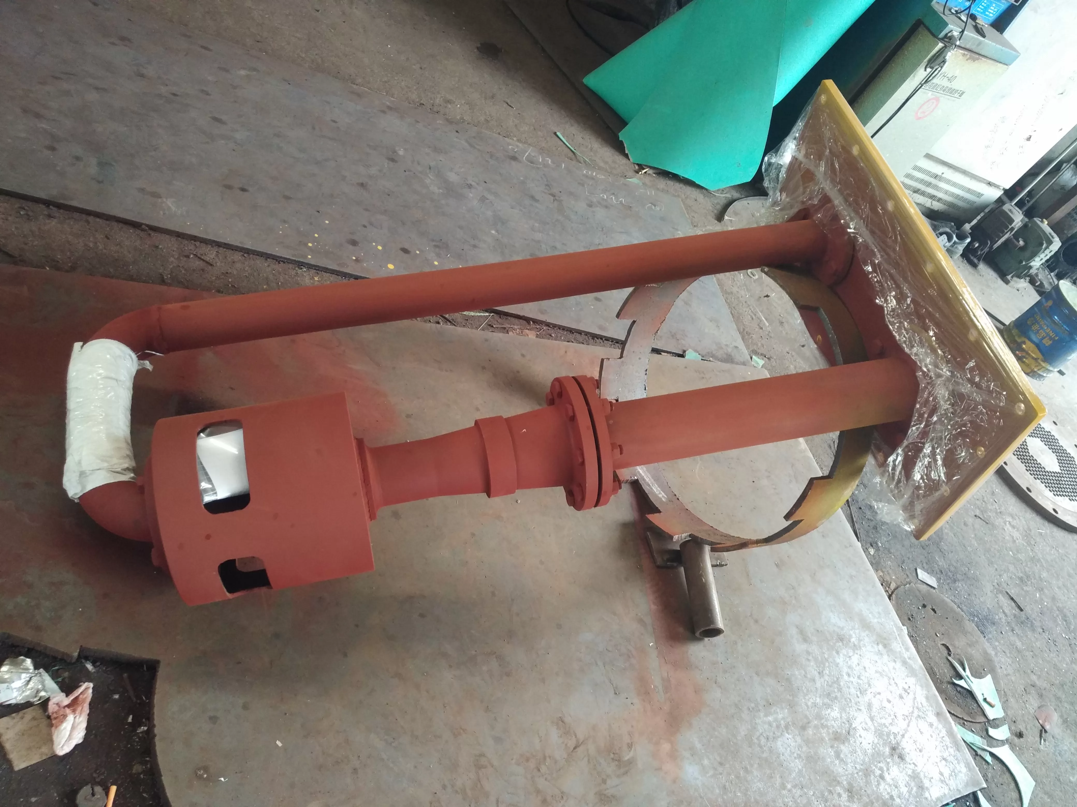
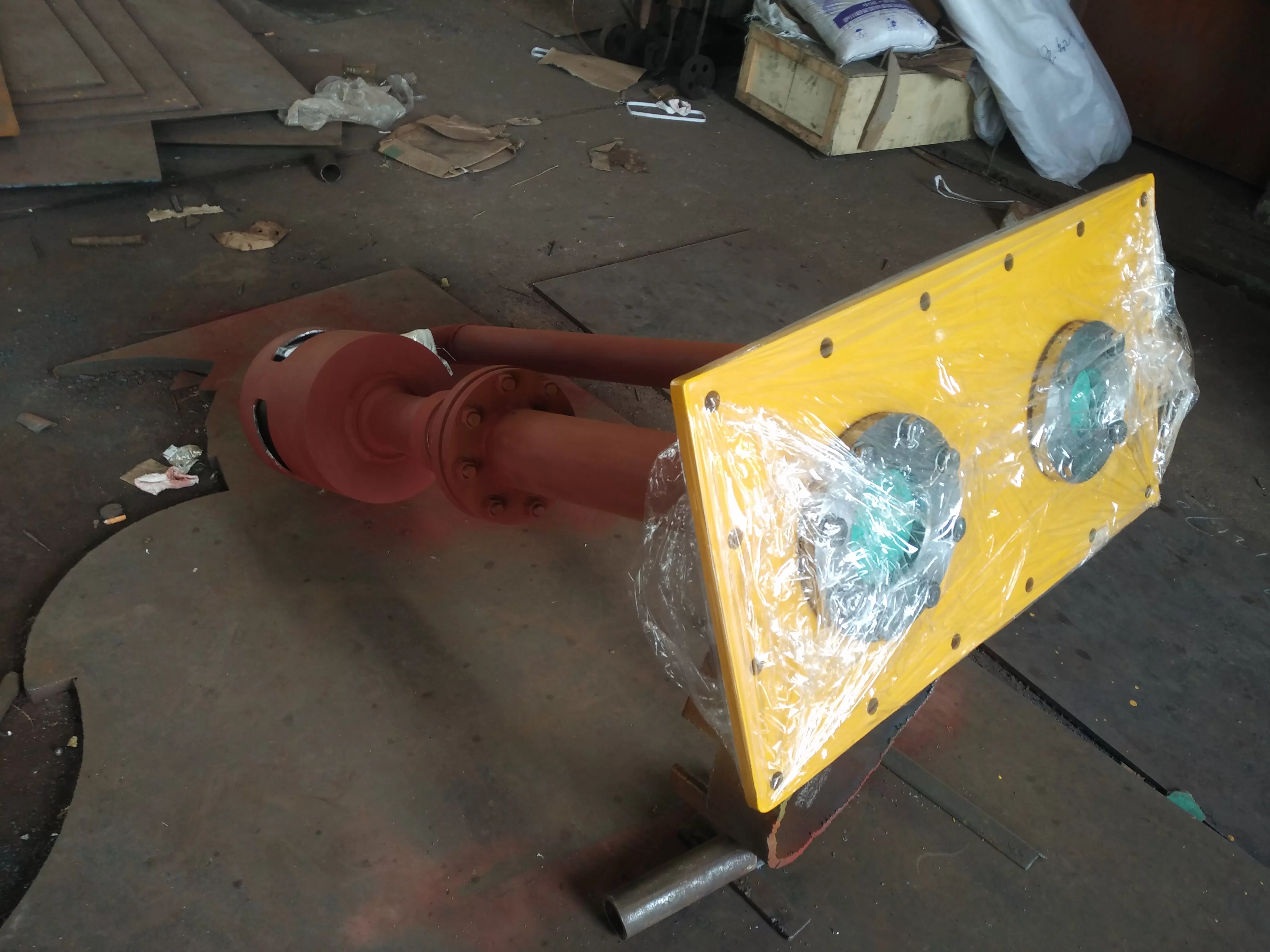
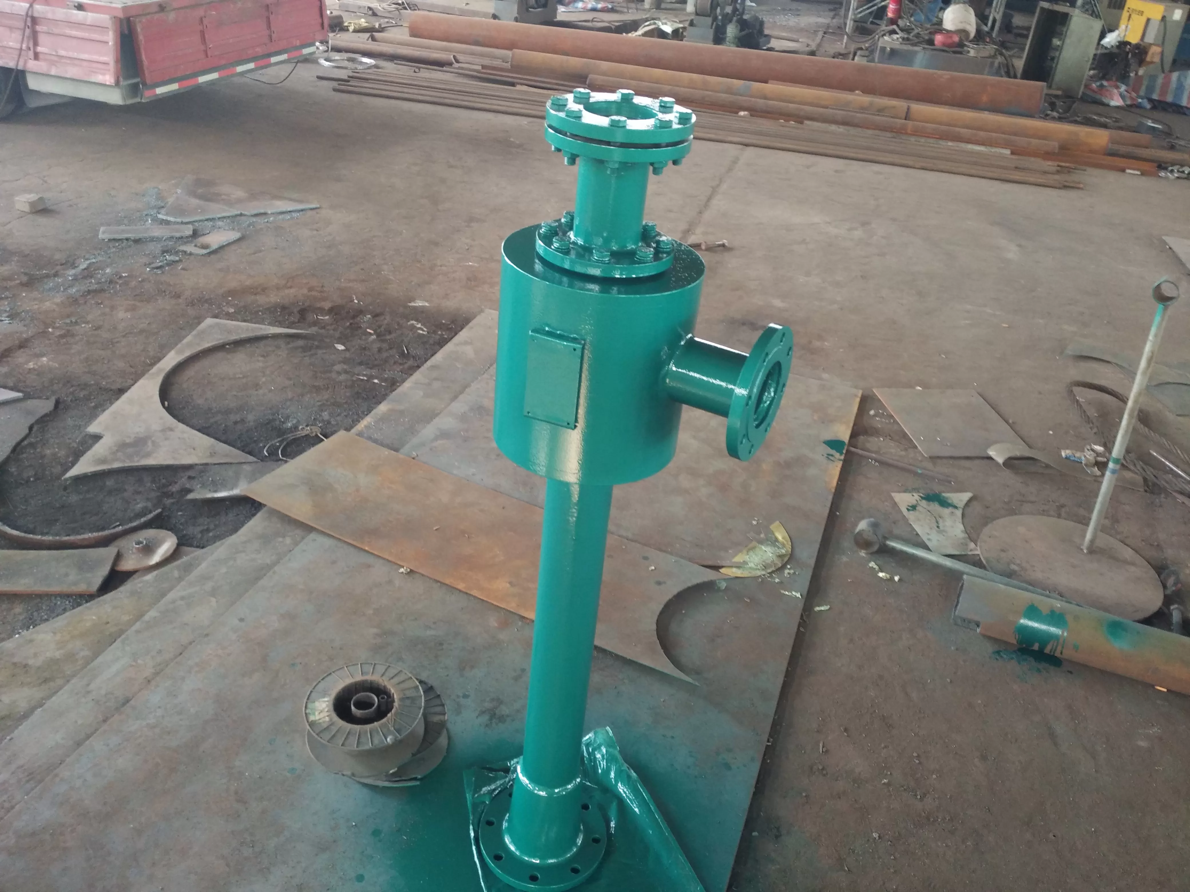
Overview of oil cooler:
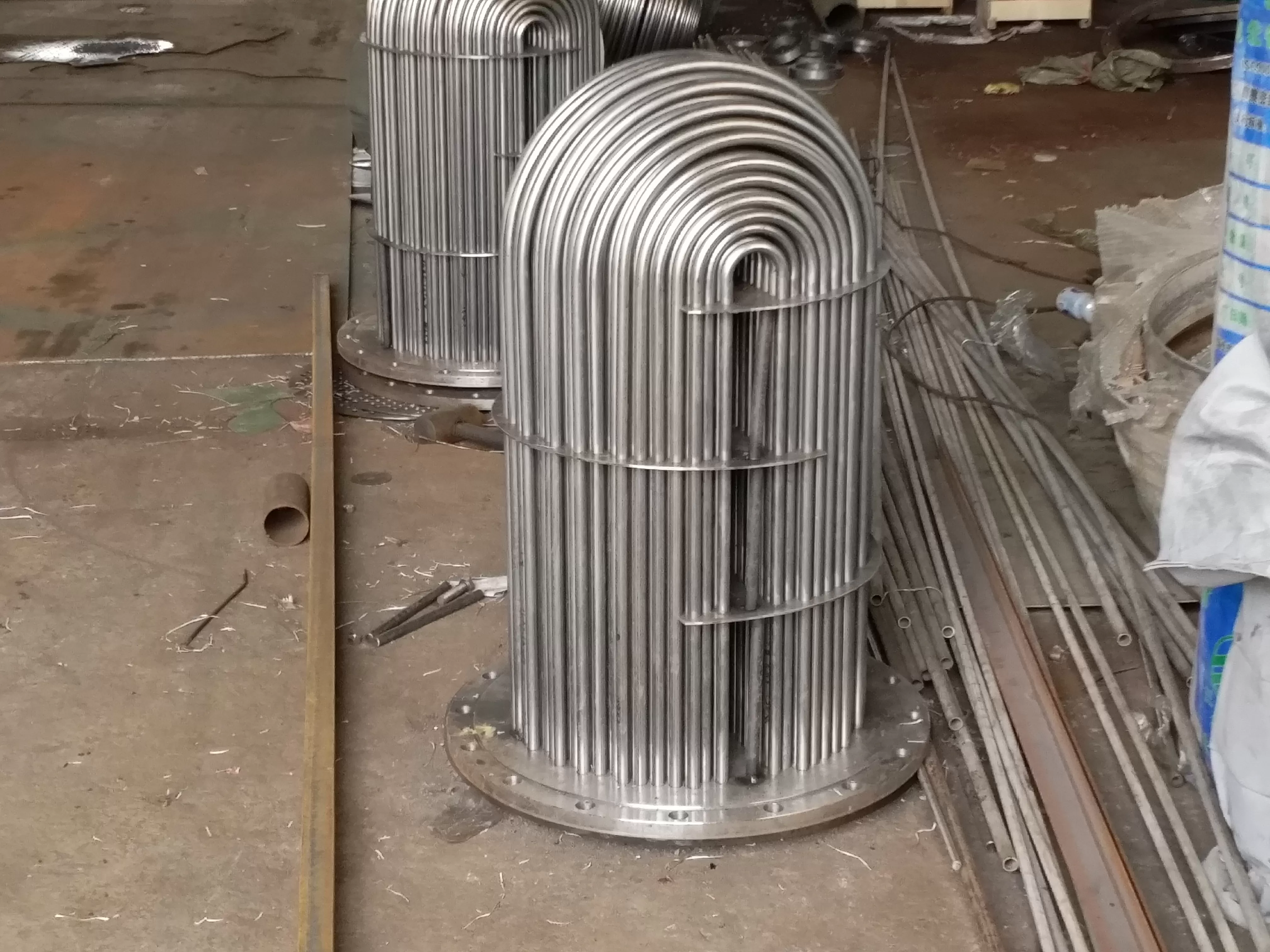
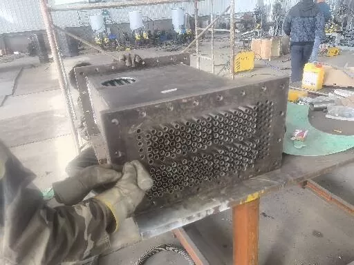
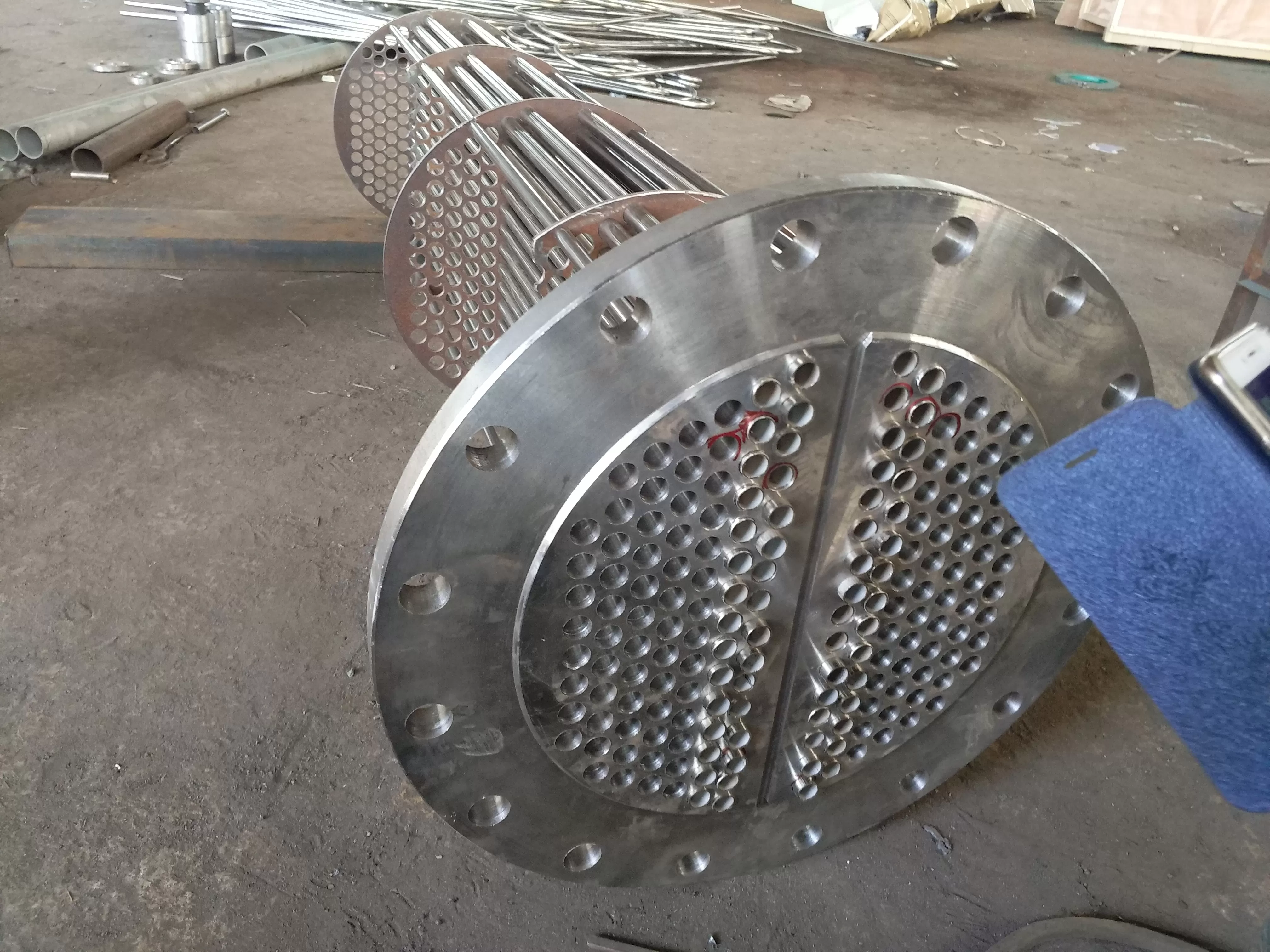
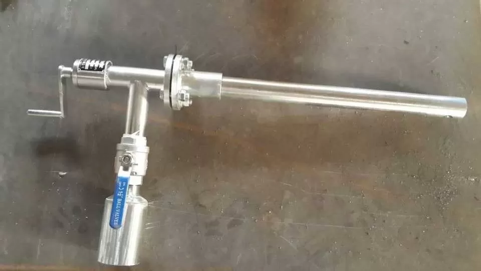
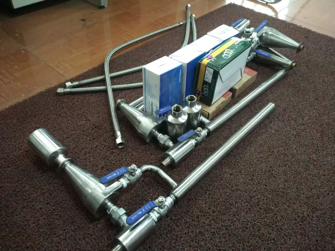
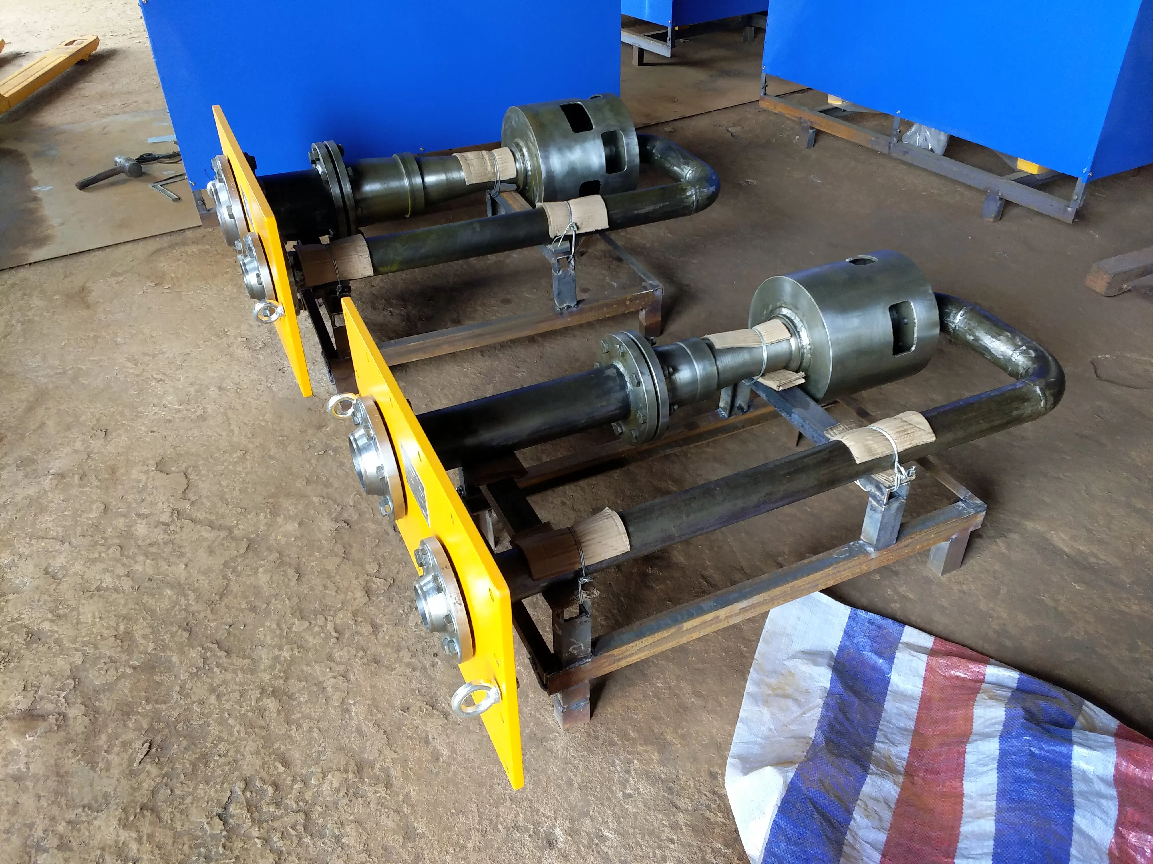
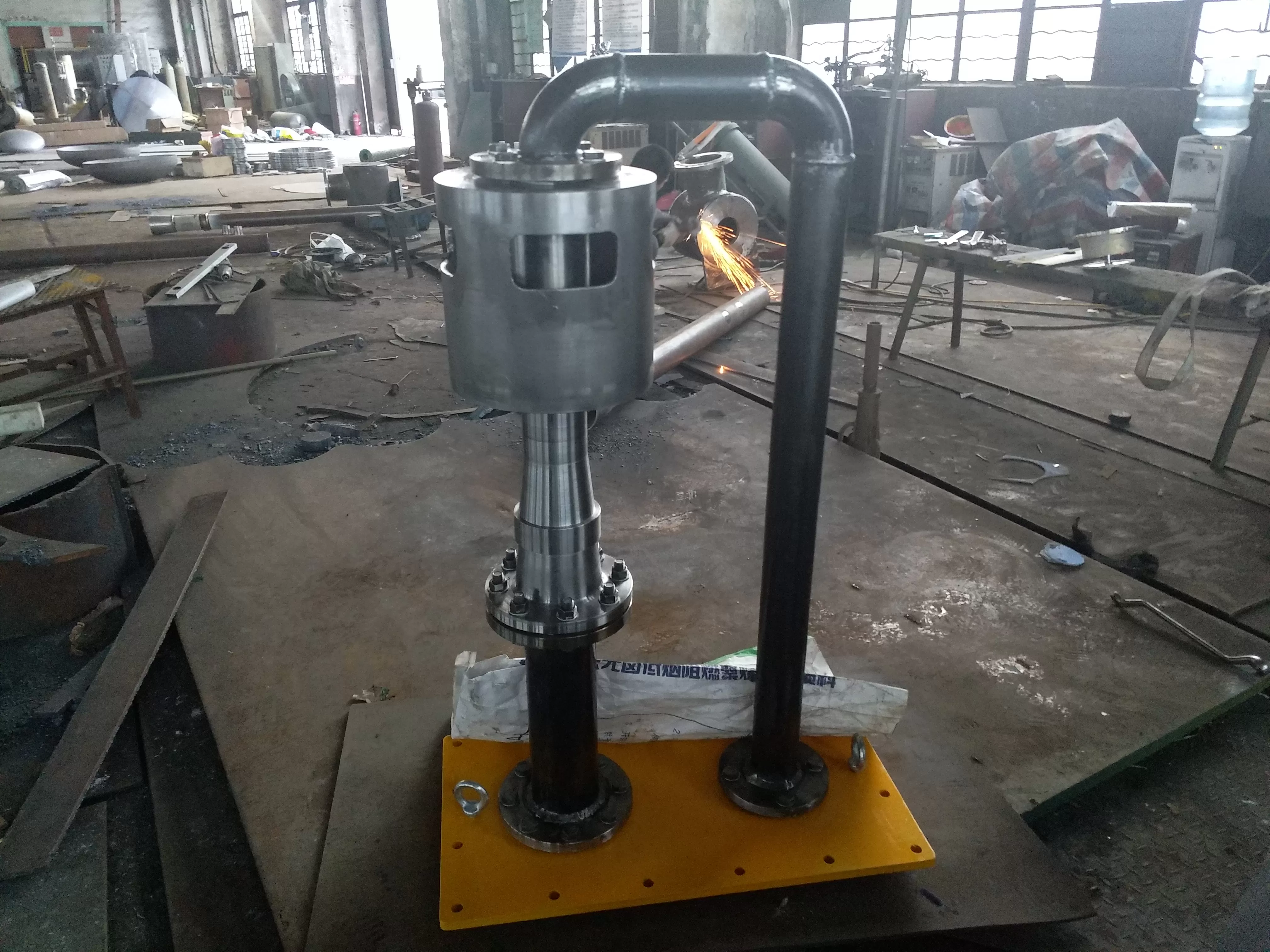
Oil cooler, also known as oil-water cooler or tube type oil cooler, is a turbine oil cooling equipment used in the power system and steam turbine. The oil cooler is a smooth surface type and uses circulating water as the medium for on-site heat exchange to ensure that the inlet oil temperature of the bearing reaches the specified value and ensure the normal operation of the unit. The main components of a vertical oil cooler include an upper and lower water chamber, a shell piping system, and an oil filling pipeline assembly. The shell is connected to an inlet and outlet water pipe, an inlet and outlet oil pipe, a drainage pipe, an exhaust pipe, and a temperature gauge seat. The cooling water process is generally a dual process, and the oil cooler is usually installed vertically or horizontally (with the option of a horizontal oil cooler).
Selection form of oil cooler:
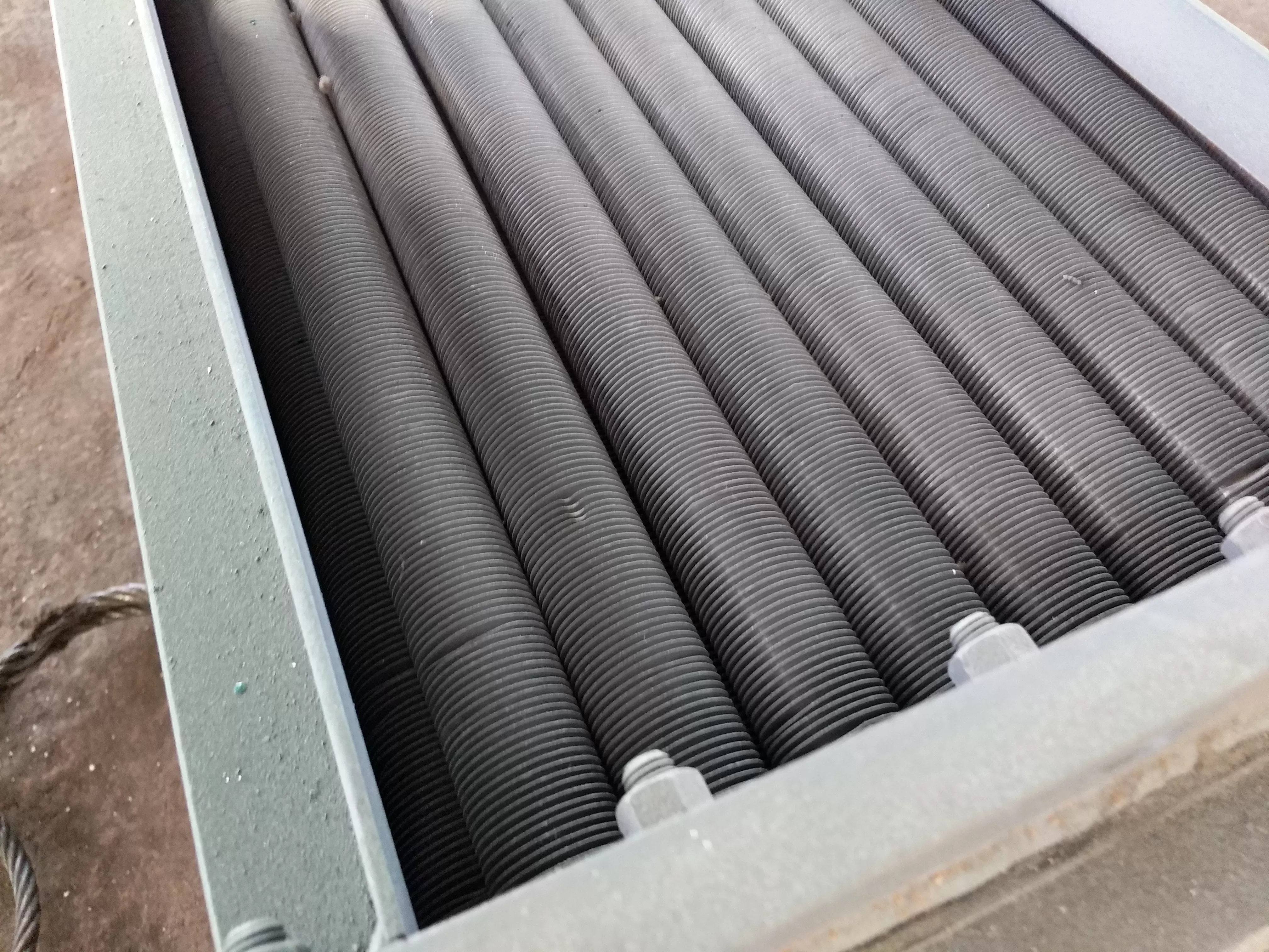
Oil water cooler selection (vertical oil cooler, horizontal oil cooler) - The cooling area should be informed, and the cooling form can be divided into LY type light tube (for use) and LYC type fin type. Generally, purple copper is selected for heat exchange cooling pipes, and other steel pipes such as stainless steel pipes, brass pipes, and purple copper pipes can also be selected as heat exchange components according to user needs.
Structure: The oil cooler can be installed in two types: vertical and horizontal; According to the form of cooling pipes, there are two types: light pipe type and enhanced heat transfer pipe type; According to the material of the cooling pipe, it is divided into two types: copper pipe and stainless steel. Correct selection should be made according to different occasions, usage requirements, etc.
Analysis of the causes of oil cooler failure:
During the operation of the unit, # 1, # 2, # 5, and # 6 units experienced water or oil faults at the bottom cover of the oil cooler, especially during the start-up or shutdown of the unit, and the faults occurred frequently. The 删除lation between oil and water in the oil cooler, as well as the leakage of oil and water, all rely on two O-ring seals. If the two O-rings are damaged or displaced, causing a change in clearance, it can lead to leakage. Because the cover of the O-ring is on the left and right sides, rather than the upper and lower sides of the transmission, once leakage occurs, increasing the tightening force of the flange bolt cannot reduce the leakage amount.
After analysis, the following reasons that can easily cause changes in the clearance and damage of the O-ring seal of the oil cooler have been summarized:
1) During the start-up or shutdown process of the unit, pressure fluctuations occur on the oil and water sides of the oil cooler, causing the O-ring of the oil cooler to move and causing leakage.
2) During the installation of the unit, if there is eccentric installation inside the oil cooler, it will cause abnormal clearance between the O-ring seal of the oil cooler. During operation, slight pressure fluctuations (oil side, water side) can cause leakage.
3) During each repair process, when replacing the O-ring seal of the oil cooler, due to the narrow position of the bottom cover, the installation is inconvenient, and often the O-ring of the oil cooler is crushed by the copper bed, resulting in leakage. After each repair, the probability of leakage on the water side is higher than that on the oil side, and it should be noted that the current design is not convenient for repair and maintenance.
Feasibility analysis of technical transformation of oil coolers:
Add a polytetrafluoroethylene pad between the bottom end cover of the oil cooler and the flange joint surface between the oil cooler and the barrel body. On the basis of maintaining the inconvenience of the original cover, add two more covers. Due to the stretchability of polytetrafluoroethylene material compared to copper bed, it meets the requirement of increasing sealing energy by relying on flange bolt tightening force. The difficulty of implementing this measure is much lower than other measures.
Economic analysis of technical transformation of oil coolers:
1) Every time the oil cooler leaks, it usually needs to wait until the unit undergoes major and minor repairs to carry out the repair work. In the stage of operation with damage, the cleaning work of the leaked oil and water is increased, which increases the workload of the team.
2) The end cover of the oil cooler has a large volume and limited repair space, so each time when installing the O-ring of the tubular oil cooler, 5 people need to work simultaneously, which results in a considerable labor cost for each repair.
3) Repair - Replacing the O-ring seal of the oil and water cooler often generates a lot of consumables, which increases the cost of repair. Based on the above analysis, it can be concluded that the technical transformation of the oil cooler is necessary and feasible, as well as the economic benefits it can bring after the transformation. During the renovation of the tubular oil cooler, a gradual approach can be adopted, utilizing unit maintenance to gradually retrofit the oil coolers of units # 1, # 2, # 5, and # 6. After the renovation, it is possible to bring corresponding economic benefits and save equipment maintenance and repair costs.
Oil cooler -:
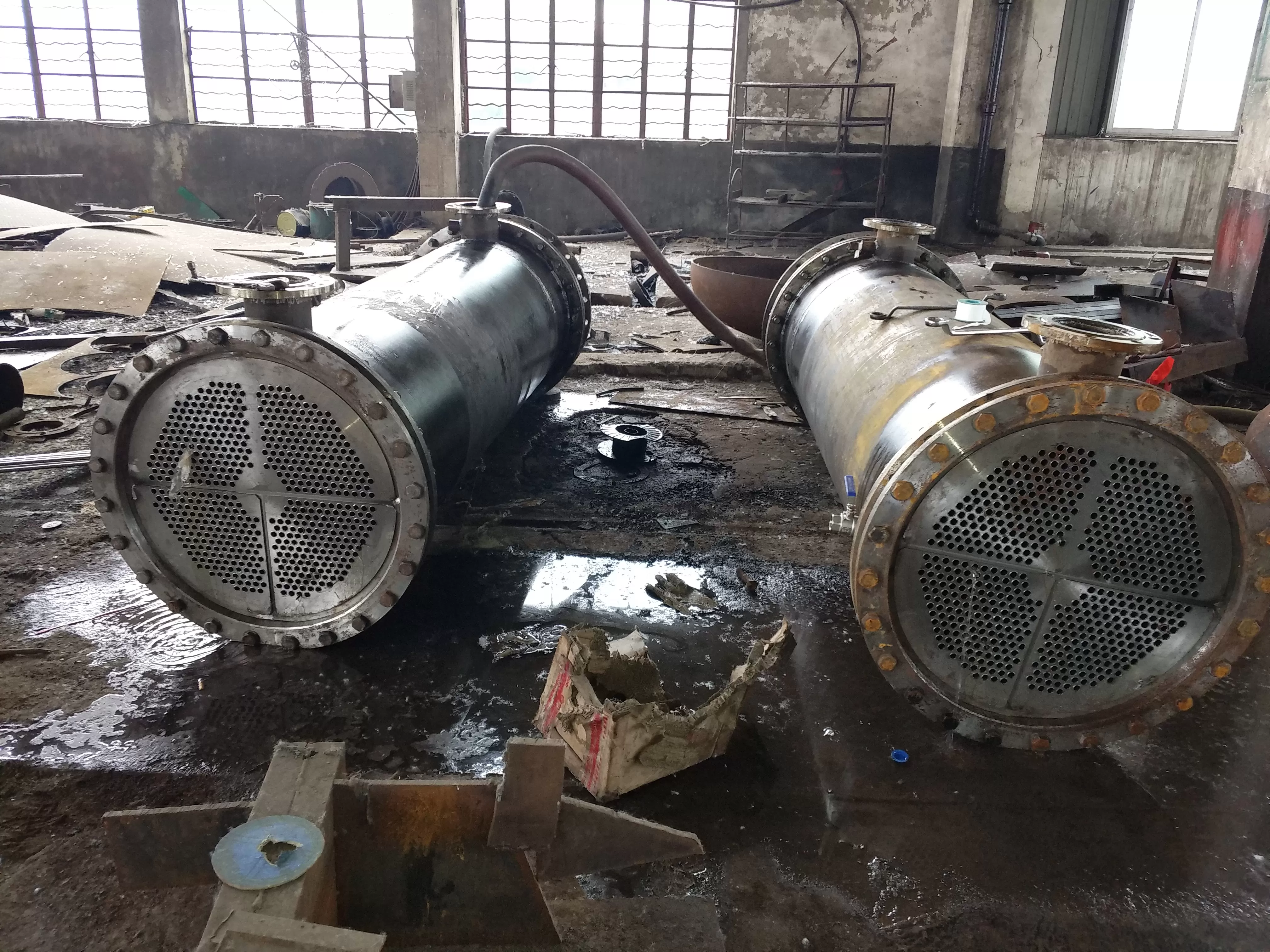
1. The oil cooler uses copper tubes as heat exchange elements, with high heat transfer coefficient, large heat area per unit length, and high heat transfer.
2. The structure of the oil-water cooler is reasonable and can maintain stable oil temperature within a large range of temperature changes, with good resistance to temperature changes and vibration.
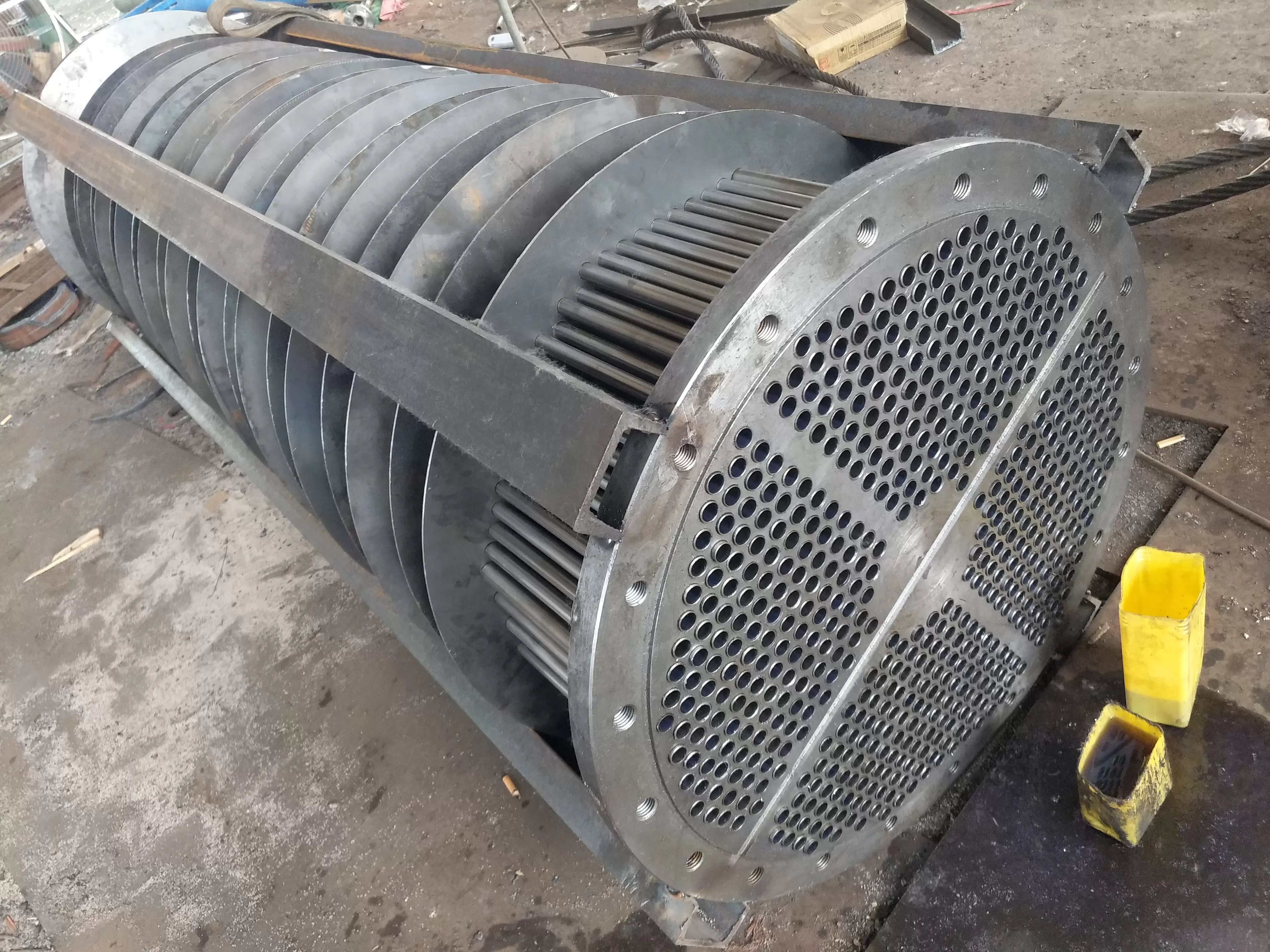
3. The assembly structure of the tubular oil cooler is reliable, ensuring that cooling water does not enter the steam turbine unit.
4. The steel pipe bundle of the oil cooler is smooth, prickly, wrinkled, and not easily dusty or scaled, with low fluid resistance.
Selection of heat exchange tube cooling tube for tubular oil cooler -:
1. The heat exchange tube of the oil-water cooler can be made of thin-walled stainless steel pipes with a diameter of 0.5-0.7mm, which improves the overall heat transfer energy. Under the same heat transfer area, the overall heat transfer coefficient is 2.121-8.408% higher than that of copper pipes.
2. The tube type oil cooler pipes can be made of copper pipes or stainless alloy steels such as TP304, TP316, TP316L, etc., which have high hardness and significantly improve the rigidity of the pipes. Therefore, they have strong impact and vibration resistance to high-temperature steam.
3. After using high-quality stainless steel pipes for the oil cooler, the smooth inner wall of the pipes reduces the thickness of the bottom layer of the boundary laminar flow, which not only enhances heat transfer but also improves the ability to resist scaling.
4. In order to eliminate welding stress, all stainless steel pipes are subjected to heat treatment under protective gas at a high temperature of 1050 ℃.
5. All stainless steel pipes of the tubular oil cooler are checked for pressure difference, and the pressure is tested to 10MPa for 5 minutes before pressure drop.
6. The oil-water cooler adopts high-quality stainless steel pipes, which have strong resistance to chloride ions and low equipment cost.
Using an oil cooler - potential:
In order to ensure sufficient safety for turbine oil cooling during turbine operation, the vertical oil-water cooler and horizontal tubular oil cooler are composed of two oil coolers with the same area and a three-way valve. They can only work and be used as backup. If there is a cooling effect difference due to high oil temperature or high inlet water temperature of the unit, or when cleaning or repairing the tubular oil cooler during operation, the standby tubular oil cooler can be opened without stopping the machine.
Shortage of series and parallel oil coolers:
1. The horizontal oil-water cooler operates in series, including cooling and uniform oil temperature.
2. The shortcomings of vertical tubular oil coolers operating in series are: high oil pressure drop and inability to 删除late oil during operation.
3. The parallel operation of the oil cooler has a small decrease in oil pressure, convenient 删除lation, and can be repaired during operation.
4. The shortcomings of parallel operation of tubular oil coolers include poor cooling performance and uneven oil temperature.
Function of oil cooler:
The main function of a vertical oil-water cooler and a horizontal tubular oil cooler is to cool lubricating oil and maintain the temperature of its bearings within a positive range during the operation of steam turbines and generators# 1. The main oil coolers of Units # 2, # 5, and # 6 are manufactured by Shanghai Steam Turbine Factory. During the operation of the oil coolers, there are frequent failures of the bottom end cover oil or water. During the maintenance process, the causes of frequent failures were identified, and corresponding technical improvement measures were proposed, which has certain reference significance for the design and operation maintenance of oil coolers.
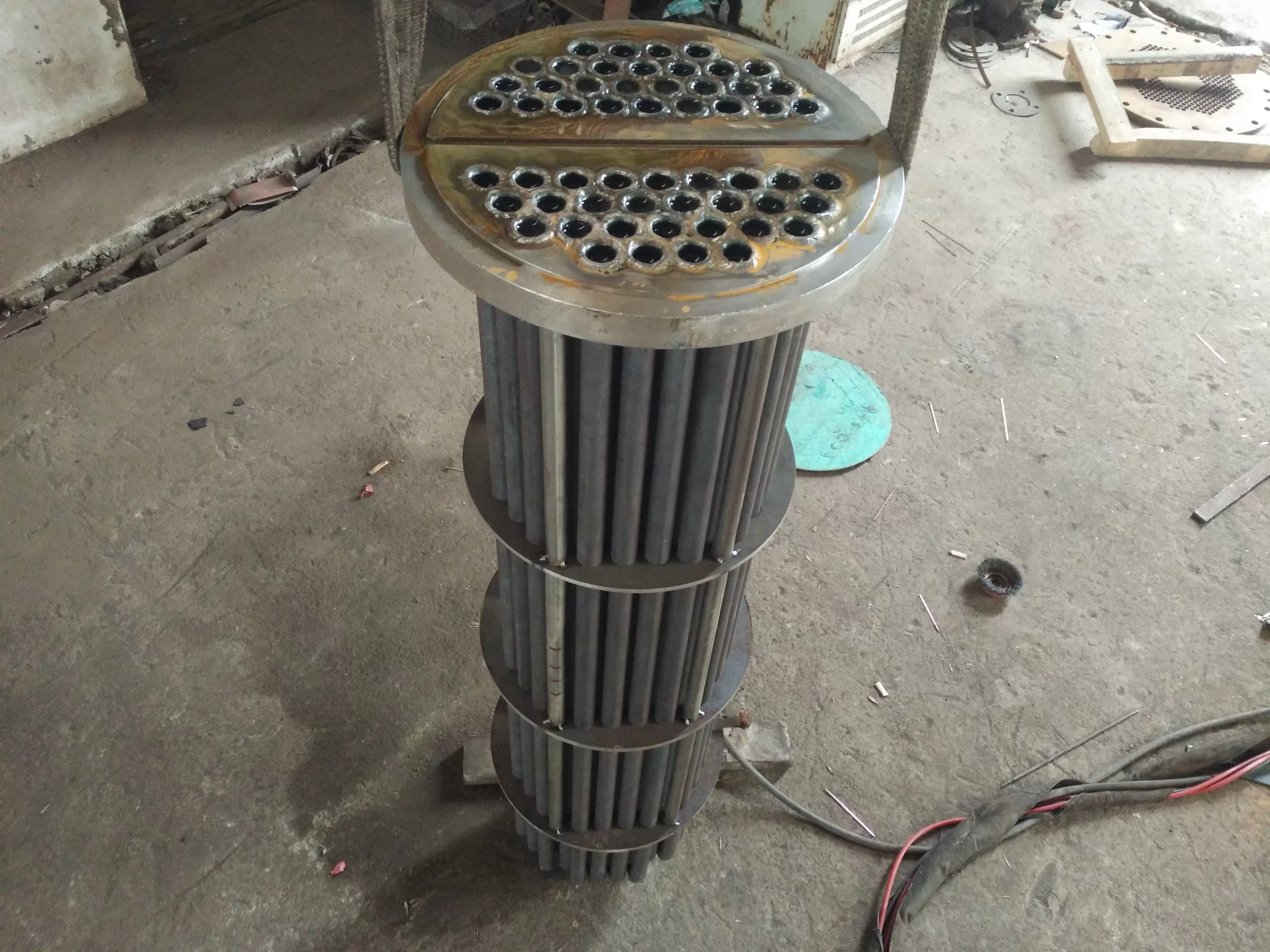
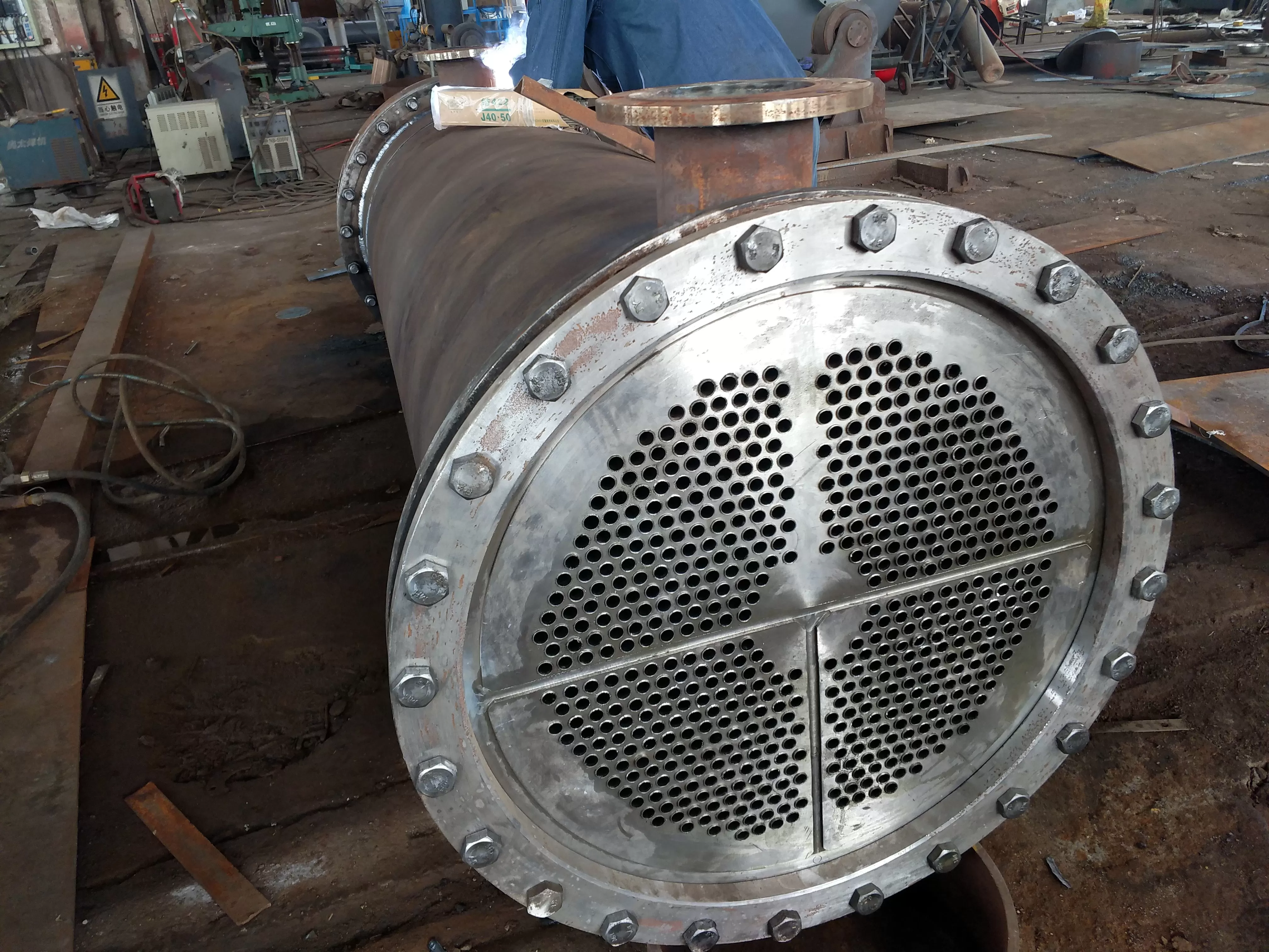
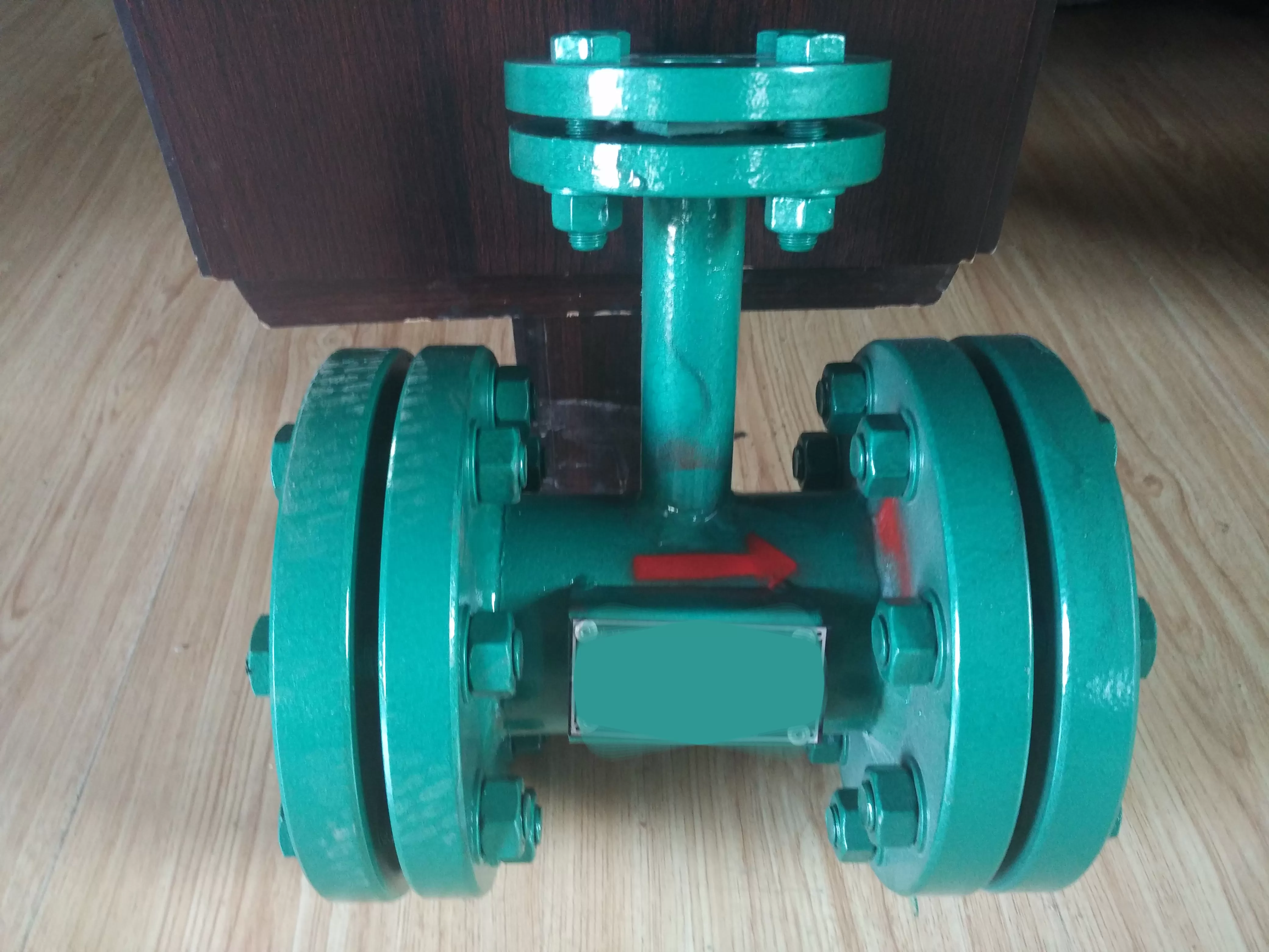
Working principle of oil cooler:
Closed cooling water enters the oil cooler through the end cap of the oil cooler, and then flows through the small pipes inside the oil cooler. The small cooling water pipes are fixed by partitions distributed inside the oil cooler. Through the partitions, the oil cooler is divided into several small spaces, and lubricating oil flows in an S-shape outside the cooling water pipes. This arrangement can increase the heat exchange area and improve the cooling effect. At the bottom of the oil cooler, a cooling water chamber is formed. Lubricating oil and cooling water are separated and sealed by two O-rings (rollers) and a copper bed.
During the normal operation of the steam turbine generator set, some work is consumed due to bearing friction. The oil cooler will convert it into heat, causing the lubricating oil temperature of the bearings to increase. If the oil temperature is too high, the bearings may experience softening, deformation, or burning accidents. In order to ensure the normal operation of the bearing, the lubricating oil temperature must be maintained within a certain range. Generally, the oil temperature entering the bearing should be between 35-45 ℃, and the discharge oil temperature of the bearing should rise to 10-15 ℃. Therefore, the oil discharged from the bearing must be cooled before it can be recycled into the bearing lubrication. The auxiliary oil cooler is used to cool the lubricating oil of the main engine. High temperature lubricating oil and low temperature cooling water undergo heat exchange in the oil cooler, and the purpose of controlling the lubricating oil temperature is achieved by adjusting the cooling water flow rate (at the same time, due to the high rotor temperature, especially on the inlet side of the high-pressure cylinder, the journal of the oil cooler also transfers heat outward, so the lubricating oil also has the function of cooling the journal).
Process requirements for replacing stainless steel pipes in oil coolers:
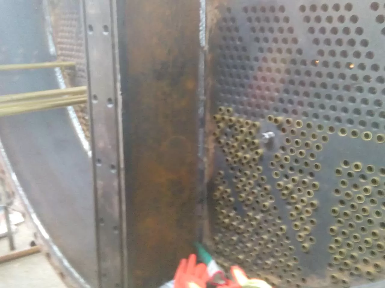
1. Preparation for replacing stainless steel pipes in a tubular oil cooler: Cut the qualified stainless steel pipes according to the size of the oil cooler. The stainless steel pipes should be 4-5 millimeters longer than the pipe plate. Remove burrs from both ends of the stainless steel pipes, polish the expanded parts smooth, and perform tempering treatment at about 50 millimeters from both ends.
2. Remove (dismantle) the old copper or stainless steel pipes of the oil-water cooler: Use a semi-circular triangular chisel to remove them. When removing, be careful not to damage the tube plate. Polish the stainless steel pipes, remove the old stainless steel pipes, clean the tube plate holes, polish them with a fine sandcloth, and wipe off the dust with a cloth.
3. After the tube plate and stainless steel tube are prepared, the tube type oil cooler can be inserted into the stainless steel tube. Be careful not to use too much force or force, align it with its own hole position, and install it. The exposed parts at both ends of the tube should be equal. The diameter of the tube plate hole is slightly larger than the tube diameter, about 0.5 millimeters, and should not be too large or too small. After the stainless steel pipe is threaded, a pipe expander can be used to expand the mouth. When expanding the pipe, the force and speed should not be too large or too small. The length of the expanded pipe should be 2/3 of the thickness of the pipe plate, and should not be greater than the thickness of the pipe plate. After the expansion is completed, both ends should be flanged with a punch.
4. When replacing the stainless steel pipes of the oil-water cooler, it is necessary to replace them half by half, and then disassemble the other half.
5. The welded joints of the tubular oil cooler after pipe replacement need to undergo leakage or damage testing.
When selecting an oil cooler, the cooling area and other parameters should be informed:
1. According to the form of cooling pipes, there are LY type light tube type (- use) and LYC type fin type.
2. According to the material of cooling pipes, they are divided into three types: carbon steel, stainless steel pipes (TP304, TP304L, TP316, TP316L), and copper pipes (T2, HSN70-1, H63).
3. What is the model of the steam turbine unit?
4. Cooling oil quantity?
5. Cooling area?
6. It is divided into two types according to installation form: vertical and horizontal.
7. Inform the on-site operation of the chloride ion content in the medium water for convenient pipe selection (please refer to the table below for compar删除n of the chloride ion content in the medium).
Note: The correct selection should be based on different occasions, usage requirements, etc. (or we recommend you to use the specifications).
Model parameters of steam turbine oil cooler:
| 汽轮机规格 | 冷油器型号 | 冷却面积
(m²) | 冷却油量
(t/h) | 进油设计温度
(℃) | 出油设计温度
(℃) | 设计水量
(t/h) | 配套台数 | -高工作水温
(℃) |
|
| N1.5MW | LY-10 | 10 | 8 | 55 | 45 | 25 | 1 | 33 |
| N3MW | LY-10 | 10 | 8 | 55 | 45 | 25 | 2 | 33 |
| N6MW | LY-12.5 | 12.5 | 8.7 | 55 | 45 | 25 | 2 | 33 |
| N12MW | LY-17.5 | 17.5 | 12.6 | 55 | 45 | 30 | 2 | 33 |
| N15MW | LY-20 | 20 | 12.6 | 55 | 45 | 30 | 2 | 33 |
| N20MW | LY-30 | 30 | 27 | 55 | 45 | 65 | 2 | 33 |
| N25MW | LY-35 | 35 | 30 | 55 | 45 | 85 | 2 | 33 |
| N30MW | LY-42 | 42 | 36.9 | 55 | 45 | 102 | 2 | 33 |
| N50MW | LY-48 | 48 | 40 | 55 | 45 | 112 | 2 | 33 |
| N100MW | LY-55 | 55 | 47 | 55 | 45 | 135 | 2 | 33 |
| N125MW | LY-60 | 60 | 52.8 | 55 | 45 | 150 | 2 | 33 |
| N135MW | LY-60 | 60 | 52.8 | 55 | 45 | 150 | 2 | 33 |
| N200MW | LY-75 | 75 | 72 | 55 | 45 | 170 | 2 | 33 |
| N300MW | LY-95 | 95 | 120 | 55 | 45 | 200 | 2 | 33 |
|
|
|
|
|
|
|
|
|
|
|
|
|
|
|
|
|
|
|
|
|
|
|
|
|
|
|
|
|
|
|
|
|
|
|
|
|
|
|
|
|
|
|
|
|
以下304不锈钢管/316L不锈钢管换热管规格技术参数仅供参考,详细参数电话咨询我们!以实际管束为准,可按客户要求设计相应管束!
| 材料 | O | SI | MN | P | S | NI | CR | MO | n-2000 | n-4200 |
| 304≤ | ≤0.080 | 0.75 | 2.00 | 0.040 | 0.030 | 8.00-11.00 | 18.00-20.00 | - | 2000 | 4200 |
| 304L≤ | 0.035 | 0.75 | 2.00 | 0.040 | 0.030 | 8.00-13.00 | 18.00-20.00 | - |
|
|
| 316≤ | 0.080 | 0.75 | 2.00 | 0.040 | 0.030 | 10.00-14.00 | 16.00-18.00 | 2.00-3.00 | 8300 | 9600 |
| 316L≤ | 0.035 | 0.75 | 2.00 | 0.040 | 0.030 | 10.00-15.00 | 16.00-18.00 | 2.00-3.00 | 4500 | 7043 |
| N | O | H | FC | O | AI | V | 3174 | 4150 | 4680 |
| 不锈钢管∠ | ∠0.02 | 0.05 | 0.015 | 0.25 | 0.12 | 2.5-3.5 | 2.0-3.0 |
|
|
|
| 型号 |
|
| 1 | Φ14×0.5 | Φ14×0.6 | Φ14×0.7 | Φ14×0.8 |
|
|
|
| 2 | Φ15×0.5 | Φ15×0.6 | Φ15×0.7 | Φ15×0.8 |
|
|
|
| 3 | Φ16×0.5 | Φ16×0.6 | Φ16×0.7 | Φ16×0.8 |
|
|
|
| 4 | Φ18×0.5 | Φ18×0.6 | Φ18×0.7 | Φ18×0.8 |
|
|
|
| 5 | Φ19×0.5 | Φ19×0.6 | Φ19×0.7 | Φ19×0.8 |
|
|
|
| 6 | Φ20×0.5 | Φ20×0.6 | Φ20×0.7 | Φ20×0.8 | Φ20×1.0 |
|
|
| 7 | Φ22×0.5 | Φ22×0.6 | Φ22×0.7 | Φ22×0.8 | Φ22×1.0 | Φ22×1.2 |
|
| 8 | Φ25×0.5 | Φ25×0.6 | Φ25×0.7 | Φ25×0.8 | Φ25×1.0 | Φ25×1.2 | Φ25×1.5 |
| 9 | Φ26×0.5 | Φ26×0.6 | Φ26×0.7 | Φ26×0.8 | Φ28×1.0 | Φ28×1.2 | Φ28×1.5 |
| 10 |
| Φ30×0.6 | Φ30×0.7 | Φ30×0.8 | Φ30×1.0 | Φ30×1.2 | Φ30×1.5 |
| 11 |
|
| Φ32×0.7 | Φ32×0.8 | Φ32×1.0 | Φ32×1.2 | Φ32×1.5 |
不锈钢管各种型号化学成分对照表:
| 管材型号规格 | 碳 | 锰 | 磷
(P) | 硫
(S) | 硅
( Si ) | 镍
( Ni ) | 铬
(CR ) | 钼
(Mo) |
| C | Mn |
| 304 | ≤0.08 | ≤2.00 | ≤0.035 | ≤0.03 | ≤0.1 | ≤8.00-10.50 | ≤18.00-20.00 |
|
| 304L | ≤0.03 | ≤2.00 | ≤0.035 | ≤0.03 | ≤0.1 | ≤9.00-13.00 | ≤18.00-20.00 |
|
| 316 | ≤0.08 | ≤2.00 | ≤0.035 | ≤0.03 | ≤0.1 | ≤10.00-14.00 | ≤16.00-18.00 | 2.00-3.00 |
| 316L | ≤0.03 | ≤2.00 | ≤0.035 | ≤0.03 | ≤0.1 | ≤10.00-14.00 | ≤16.00-18.00 | 2.00-3.00 |
|
|
|
|
|
|
|
|
|
铜管与不锈钢管换热遥遥能对照表:
| 名称 |
|
| 规格 | 材质 | 总体换热系数(W/m².k) | 不锈钢管与铜管比
总体换热系数提高% |
|
|
|
|
| 铜管 |
|
| 1.0(mm) | HSn70-1A | 3682.413869 | 0 |
|
|
| 不锈钢管 |
|
| 1.0(mm) | 304,304l,316,316L | 3460.327347 | -6 |
|
|
| 不锈钢管 |
|
| 0.7(mm) | 304,304l,316,316L | 3760.628476 | 2.214 |
|
|
| 不锈钢管 |
|
| 0.6(mm) | 304,304l,316,316L | 3872.606729 | 5.214 |
|
|
| 不锈钢管 |
|
| 0.5(mm) | 304,304l,316,316L | 3992.015968 | 8.408 |
|
|
|
|
|
|
|
|
|
|
|
介质水-适应氯离子含量指标对照表:
| 管材 |
|
| H68-A | HSn70-1 | TP304,TP304L | TP316,TP316L | TP317,TP317L |
|
|
|
长期遥遥
氯离子含量
(mg/L) |
|
| ≤50 | ≤100 | ≤150 | ≤300 | ≤500 |
|
短期遥遥
氯离子含量
(mg/L) |
|
| ≤100 | ≤200 | ≤300 | ≤500 | ≤1000 |
|
|
|
|
|
|
|
|
|
|