Introduction to hydrophobic expansion vessels:
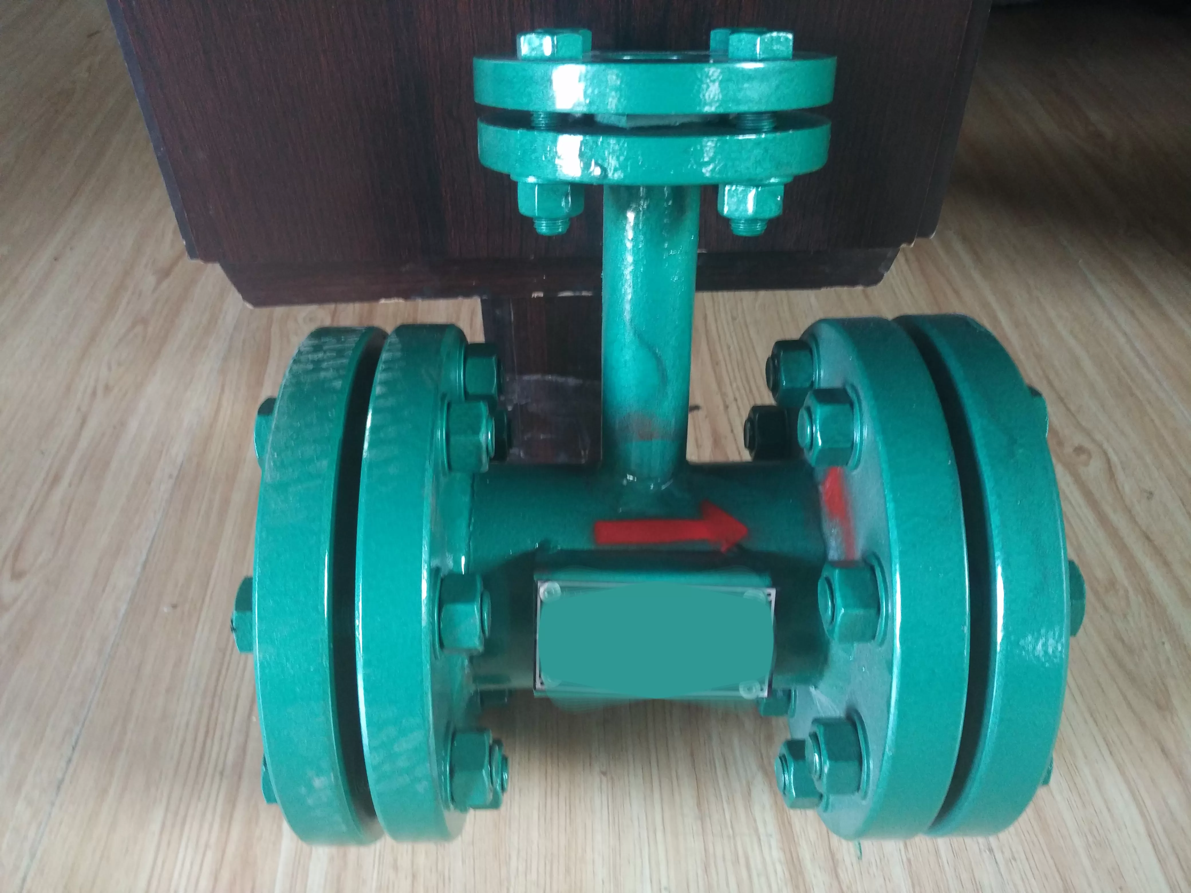
A drainage expansion vessel is a device that expands and depressurizes the drainage of the pressure drainage pipeline, separates steam and drainage, and introduces steam into a heat exchanger or deaerator to fully utilize its heat energy. The drainage is then introduced into a drainage tank, which is regularly fed into the water supply system. The main purpose is to reduce pressure. If high-pressure steam directly enters the condenser, it can easily cause pressure in the condenser. Through it, pressure can be reduced and avoided. At the same time, some of them also have a temperature reduction device that can lower the temperature. And mechanical (free float, lever float, inverted bucket) steam traps are opened and closed using the principle of buoyancy. It can automatically distinguish between steam and water, and is used to collect and reuse water that requires continuous drainage, high flow rate, and discharge. The structure of the lever float trap and the inverted bucket trap is complex, while the structure of the free float trap is simple and non vapor, and is generally used for pipe or equipment drainage;
Hydrophobic expansion container, expansion container function:
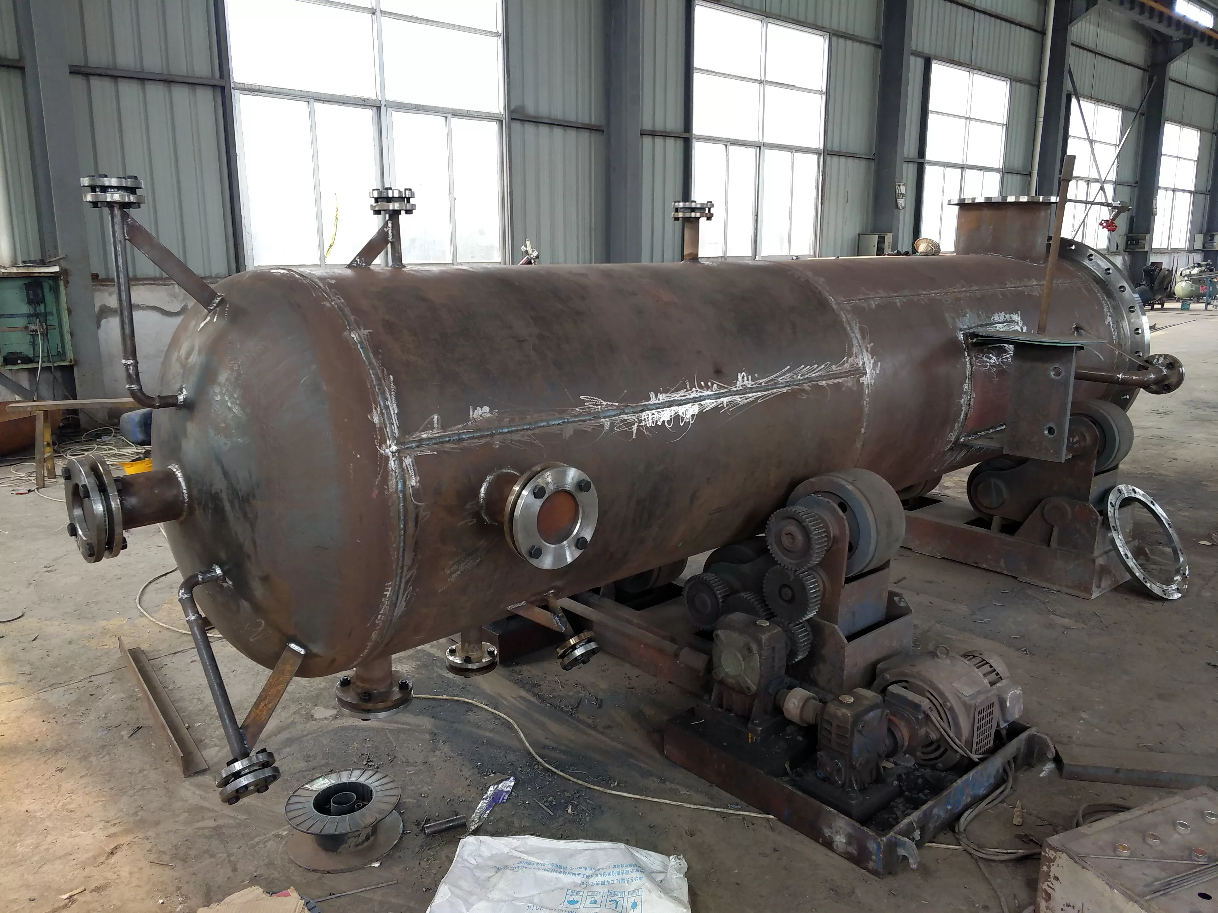
This drainage expansion vessel is composed of two 16m rectangular containers, which mainly accept the drainage of the turbine body and pipelines, as well as the drainage of high-pressure heater accidents and deaerator overflow. After the drainage enters the expansion vessel, it passes through the energy dissipation device and undergoes flash evaporation expansion and water spray cooling in the huge space of the expansion vessel, reducing its energy to the allowable value of the condenser. The steam and water after energy dissipation are respectively discharged into the throat of the condenser and the hot well, ensuring smooth drainage of the unit and pipeline, and preventing damage to the internal components of the condenser, as well as recovering the working fluid of the steam turbine. The hydrophobic expansion vessel is used for the expansion of hydrophobic pipelines under high pressure and temperature. The steam separated by the hydrophobic expansion vessel is introduced into the heat exchanger or deaerator, while the separated hydrophobic water is introduced into the drainage tank and then sent to the boiler's feedwater system.
Hydrophobic expansion vessel, expansion vessel outlet potential:
As one of the industrial equipment, hydrophobic expansion vessels play an indispensable role in industry. With the continuous development of the economy, the presence of hydrophobic expansion vessels can be seen everywhere in daily production. Therefore, in order to meet the needs of users or to understand production knowledge, and to fully utilize the role of this equipment
Hydrophobic expansion vessel, purpose of expansion vessel:
A drainage expansion vessel is a device that expands and depressurizes the drainage of a pressure drainage pipeline, separates steam and drainage, and introduces steam into a heat exchanger or deaerator to fully utilize its heat energy. The drainage is then introduced into a drainage tank, which is regularly fed into the water supply system. The main purpose is to reduce pressure. If high-pressure steam directly enters the condenser, it can easily cause pressure in the condenser. Through it, pressure can be reduced and avoided. At the same time, there is a temperature reduction device inside, which can lower the temperature. This drainage expansion vessel consists of two 16m rectangular containers, which mainly accept drainage from the turbine body and pipelines, as well as emergency drainage from high pressure heaters and overflow drainage from deaerator. After the drainage enters the expansion vessel, it passes through the energy dissipation device and undergoes flash evaporation expansion and water spray cooling in the huge space of the expansion vessel, reducing its energy to the allowable value of the condenser. The steam and water after energy dissipation are respectively discharged into the throat of the condenser and the hot well, ensuring smooth drainage of the unit and pipeline, and preventing damage to the internal components of the condenser, as well as recovering the working fluid of the steam turbine. The hydrophobic expansion vessel is used for the expansion of hydrophobic pipelines under high pressure and temperature. The steam separated by the hydrophobic expansion vessel is introduced into the heat exchanger or deaerator, while the separated hydrophobic water is introduced into the drainage tank and then sent to the boiler's feedwater system.
Installation and operation precautions for hydrophobic expansion vessels:
1. The rectangular drain flash tank, also known as the shoulder blue drain flash tank, is installed on the high-pressure condenser side and the low-pressure condenser side. The specific installation elevation and location are detailed in the condenser opening and attachment diagram of the project.
2. The drainage expansion vessel located on the high-pressure side is equipped with 12 drainage connections, which are used to receive the drainage of the steam turbine drainage system diagram - drainage header pipes a, b, c, d, e, j, g, emergency drainage of low-pressure heaters 5 #, 7 #, and 8 #, positive drainage of low-pressure heaters 8 #, exhaust ventilation valve interface, etc. The interfaces of each drainage pipe shall not be interchanged. The specific connection positions and interfaces between each drainage pipe and the drainage pipe can be found in the drainage flash tank I (drawing number M740-032000A) and the drainage system of the project - located on the low-pressure side of the drainage flash tank. There are 12 drainage pipes, which are used to receive the drainage of the drainage collection pipes h and i in the drainage system diagram. Emergency drainage of low-pressure heaters 6 #, 7 #, and 8 #, auxiliary steam drainage, deaerator overflow drainage, small steam turbine body drainage, and boiler 5% startup drainage, 1 #, 2 #, 3 # high-pressure heaters emergency drainage, etc. Each drainage connection interface shall not be interchanged. The specific interface position can be found in the drainage expansion vessel II (drawing number M740-033000A) and the drainage system diagram of the project.
3. When connecting each drainage branch pipe to the drainage main pipe, it should be arranged according to the drainage pressure of each drainage pipe. For those with higher drainage pressure connected to the same main pipe, they should be connected relatively far away from the drainage expansion vessel. For those with lower pressure, they should be connected close to the drainage expansion vessel, and each branch pipe should be connected at a 45 ° angle with the main pipe, facing the expansion vessel to ensure smooth drainage of each drainage pipe.
4. Install the expansion vessel in place, connect the pipeline and conduct a sealing test with the condenser. Expanding the container during the experiment - temporary support must be added.
When the drainage expansion vessel is put into operation, water should be sprayed simultaneously. The amount and amount of water sprayed can be controlled and adjusted through valves installed on the water spraying pipeline to ensure that the temperature inside the expansion vessel is less than 80 ℃ and the pressure is less than 0.14 MPa (a). The design water spray pressure of each expander is 1.0MPa, and the water spray rate is about 7.2Kg/s.
6. A filter screen should be installed on the water spraying pipeline, and the filter screen should not be less than 32 mesh. The filter should be cleaned regularly to prevent clogging of the spray hole.
7. The fixed screw used for transportation on the waveform expansion joint must be removed after the installation and water filling test of the expansion joint.
8. The drainage flash tank - under high load conditions - is usually during the start-up process of the unit. Therefore, during the operation of the unit, when the unit starts, stops, or the emergency drain valve of the heater is fully opened, attention should be paid to monitoring the operation status of the flash tank. When the temperature and pressure are too high or not positive, it is necessary to check the condition of each drain valve, pipeline, and filter screen of the steam turbine in a timely manner and handle it in a timely manner. Master the operating rules of the drain expander, set the opening size of the spray valve, and achieve maintenance.
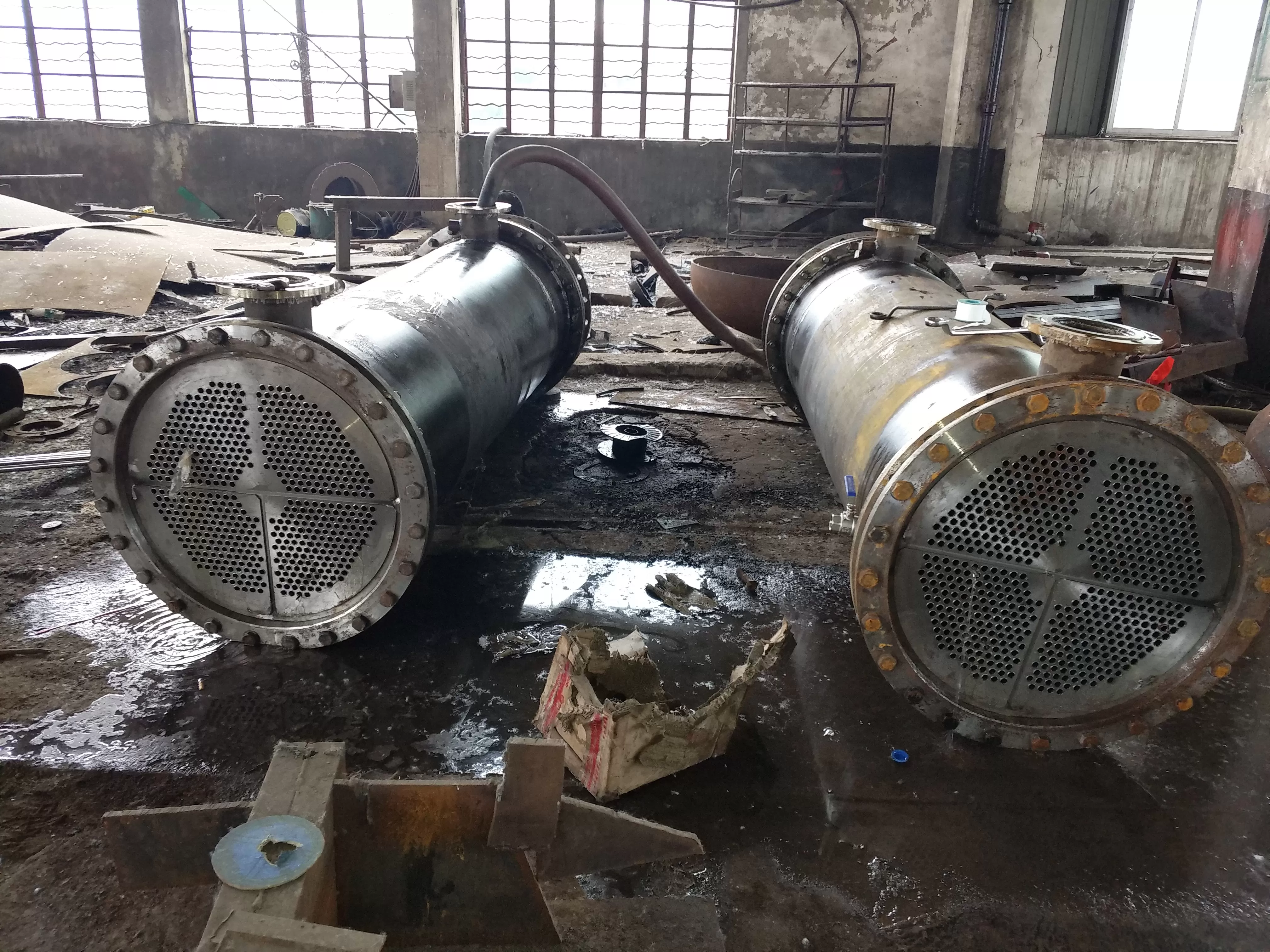
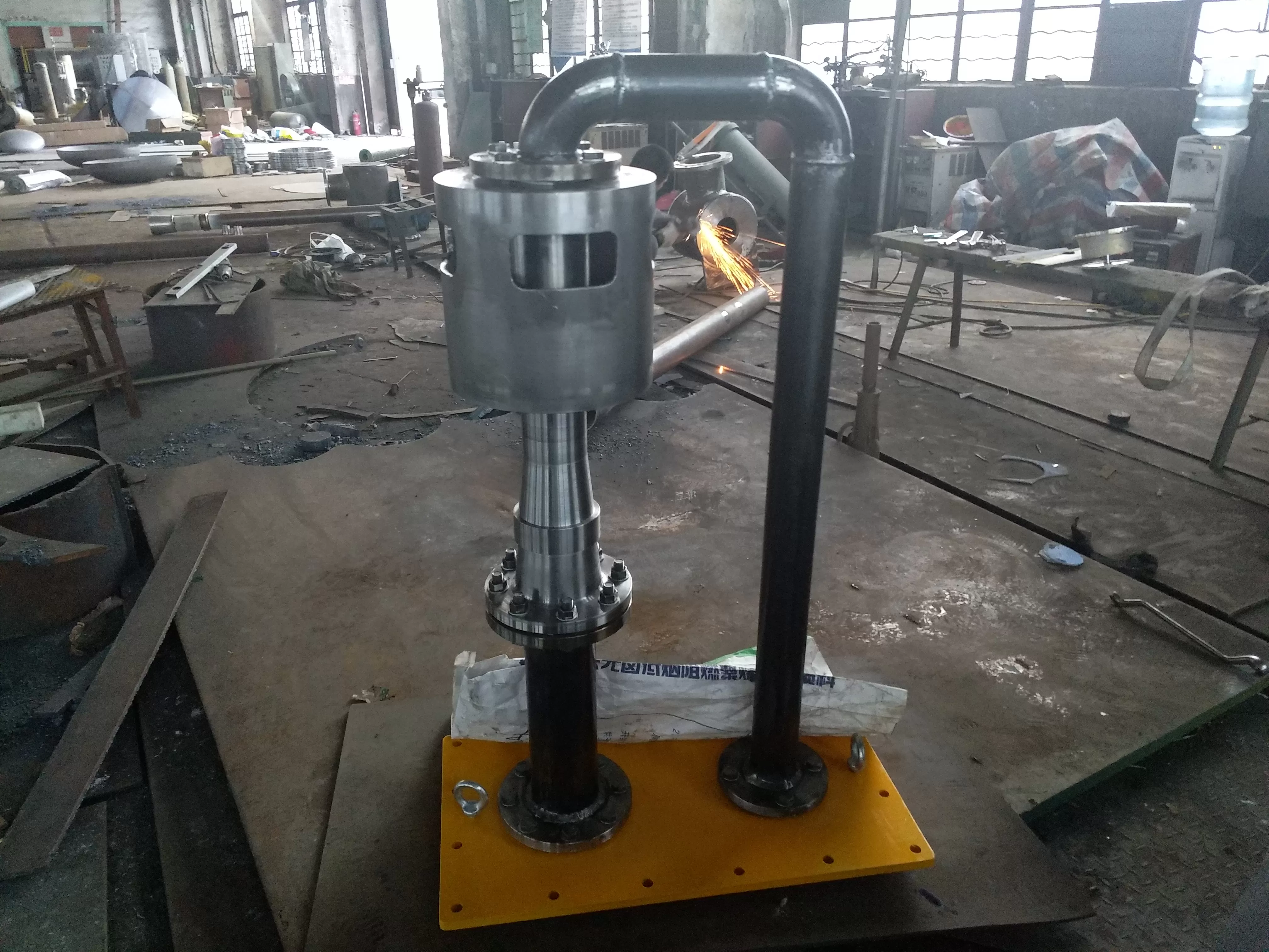
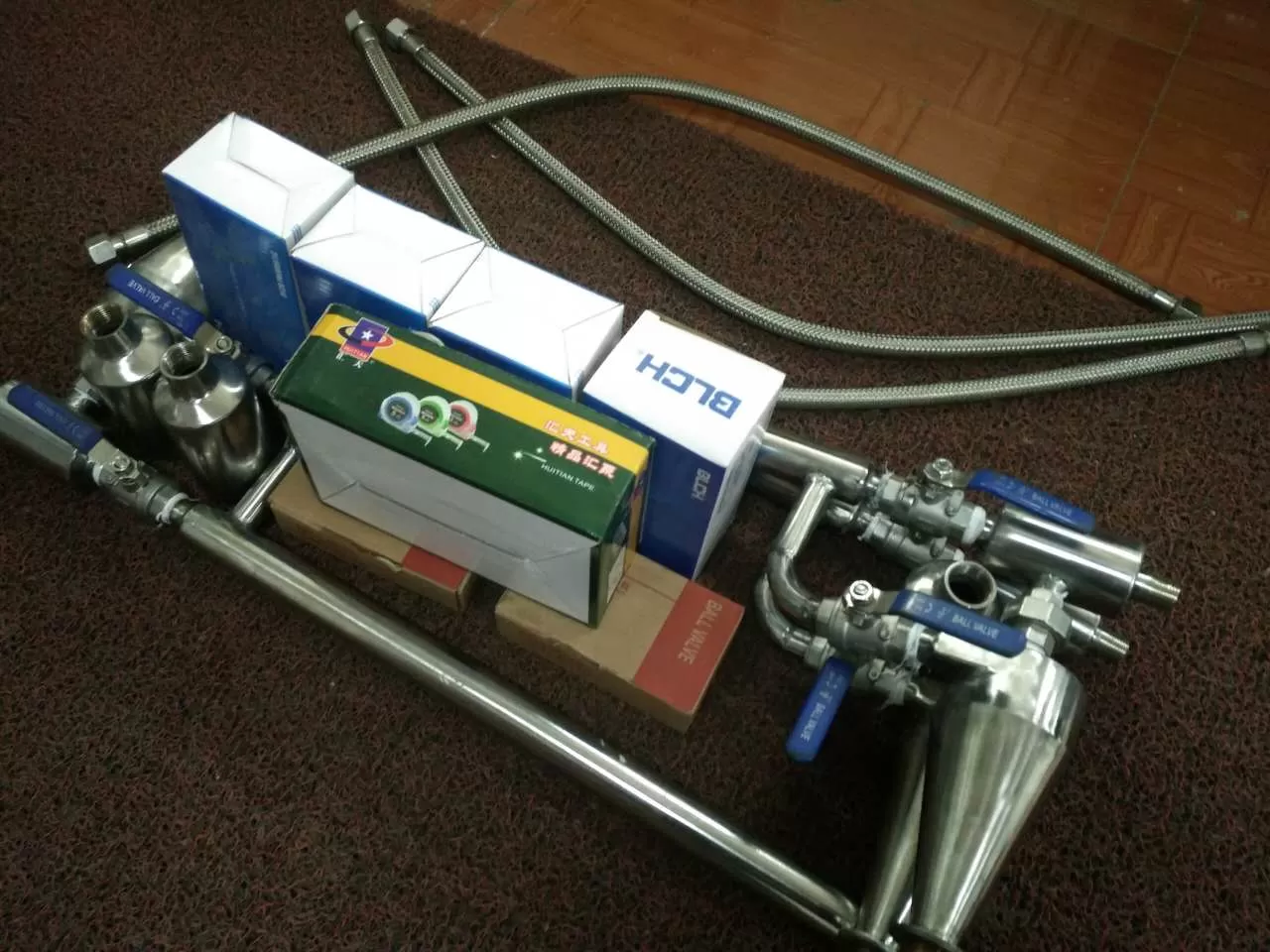
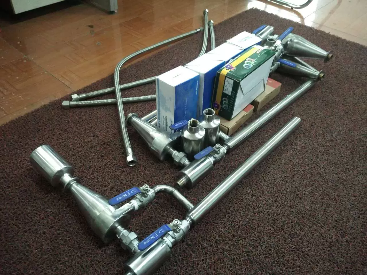
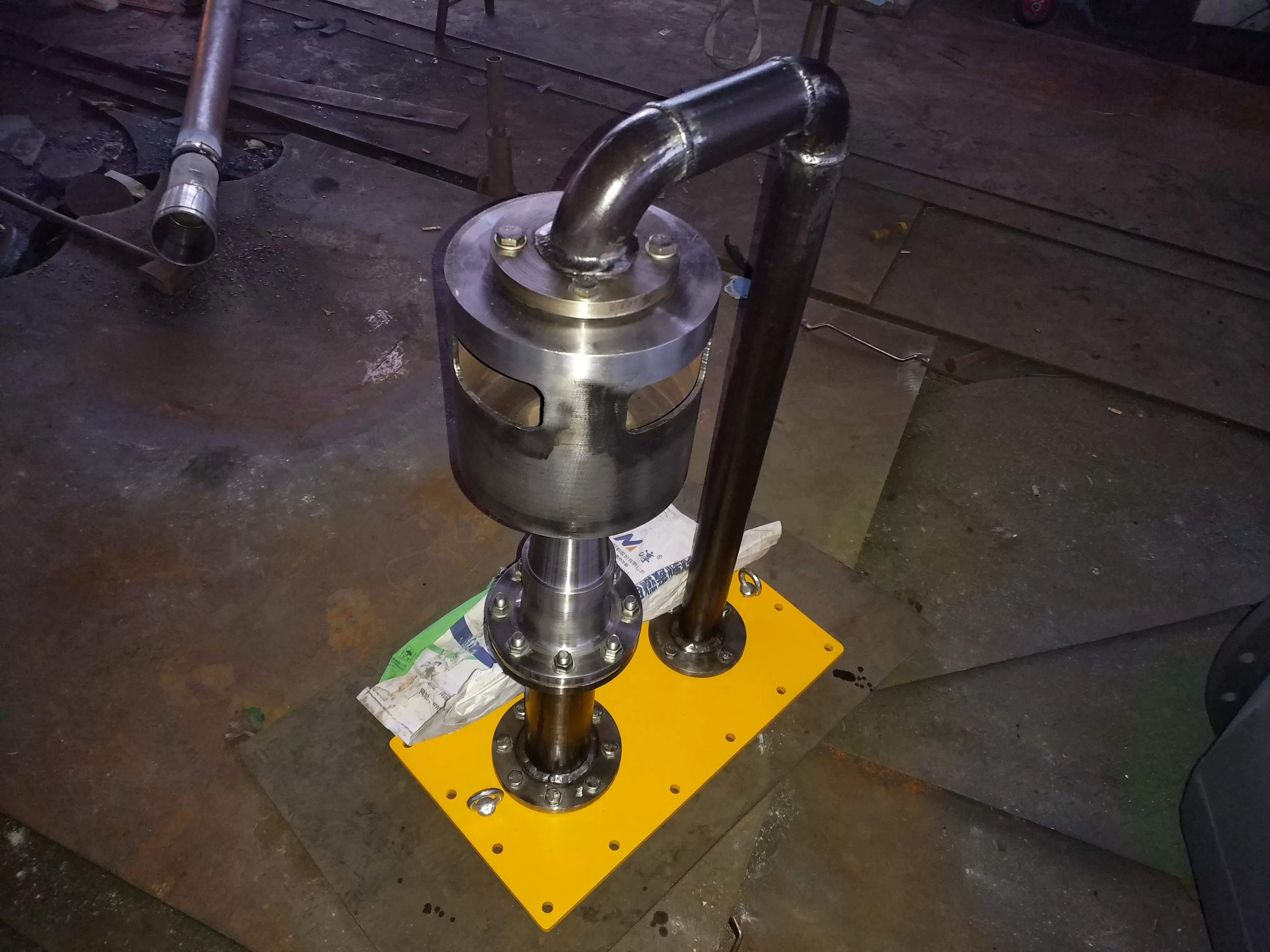
Hydrophobic expansion vessel, expansion vessel structure and working principle:
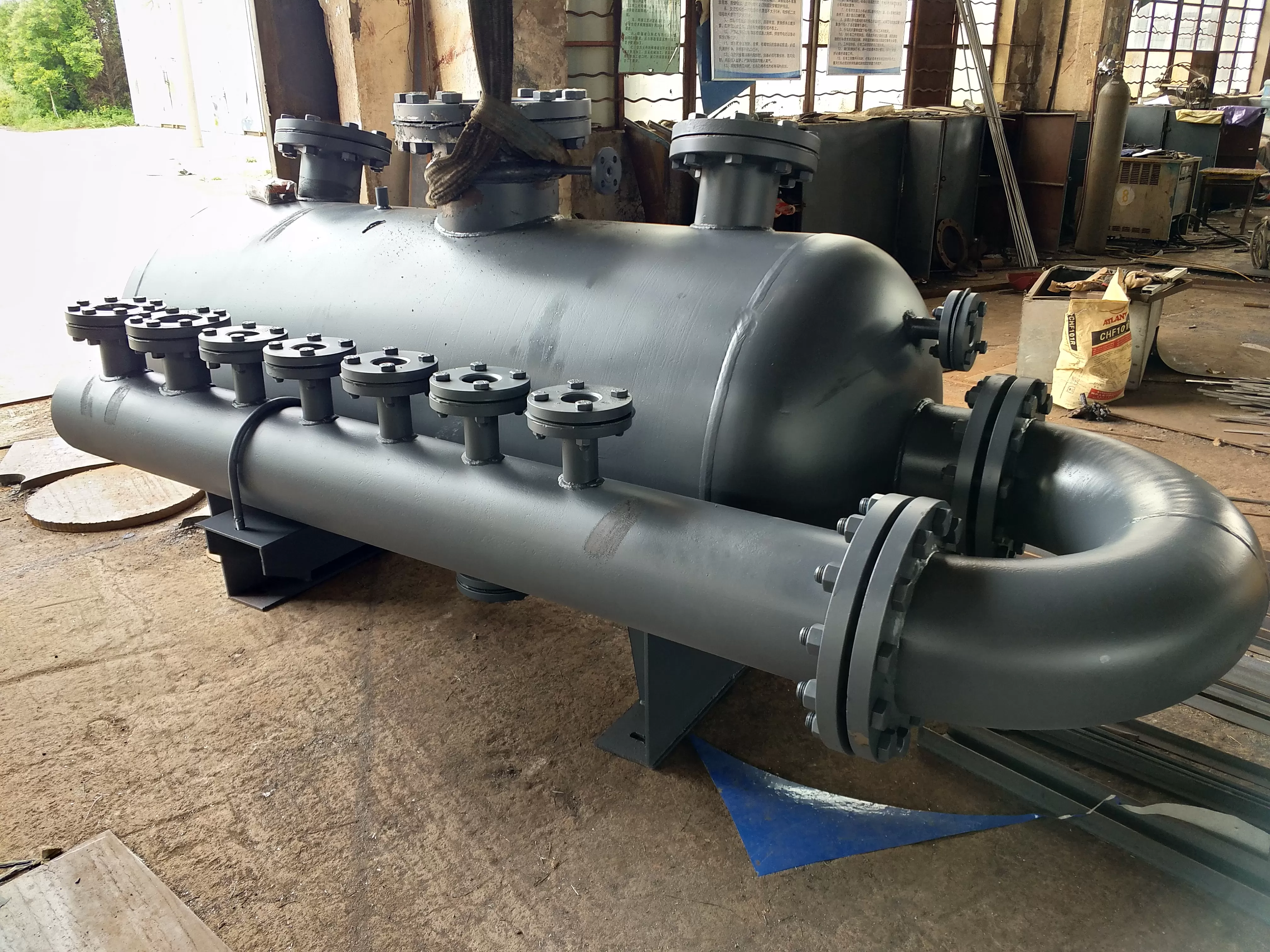
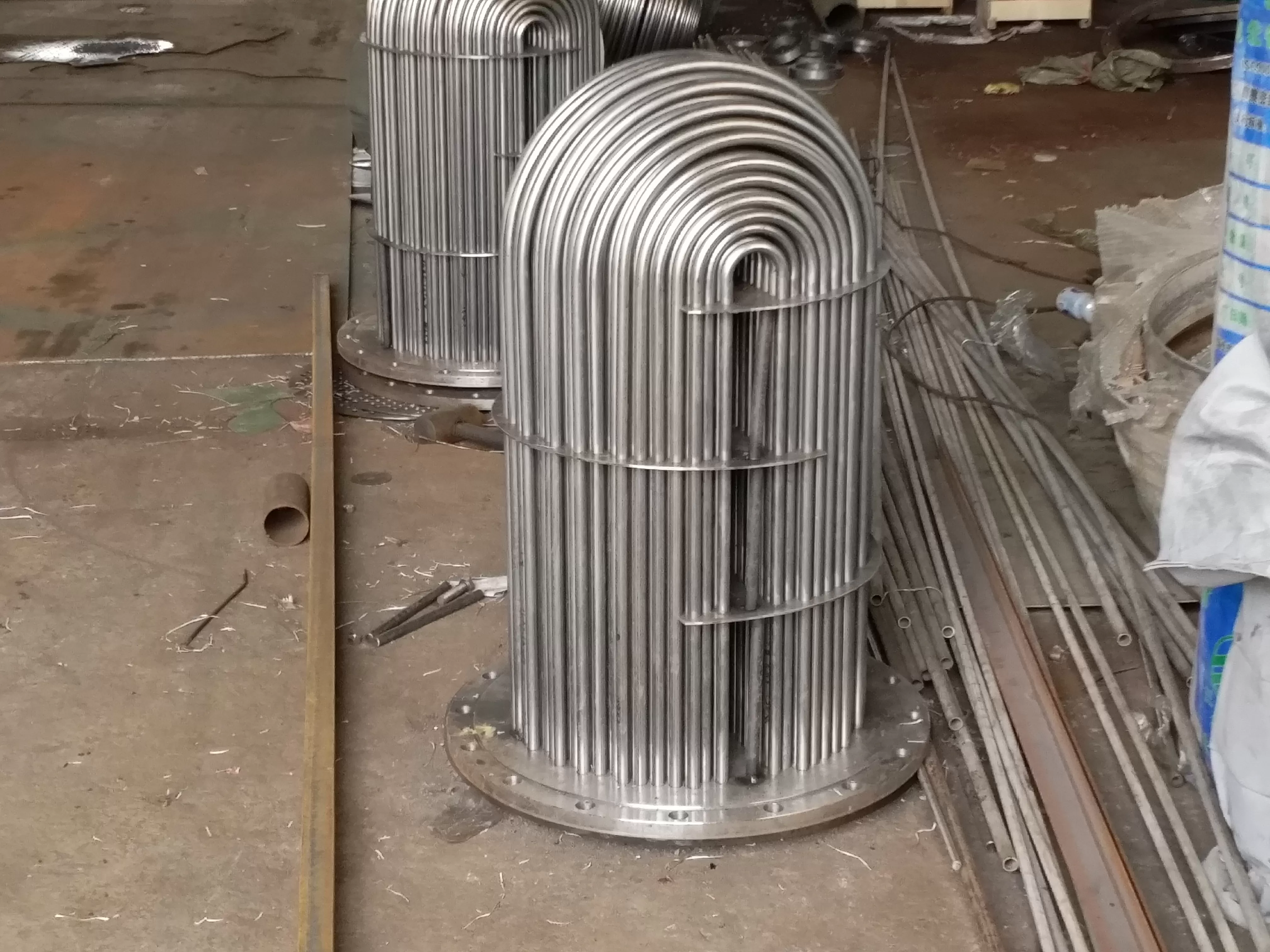
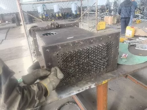
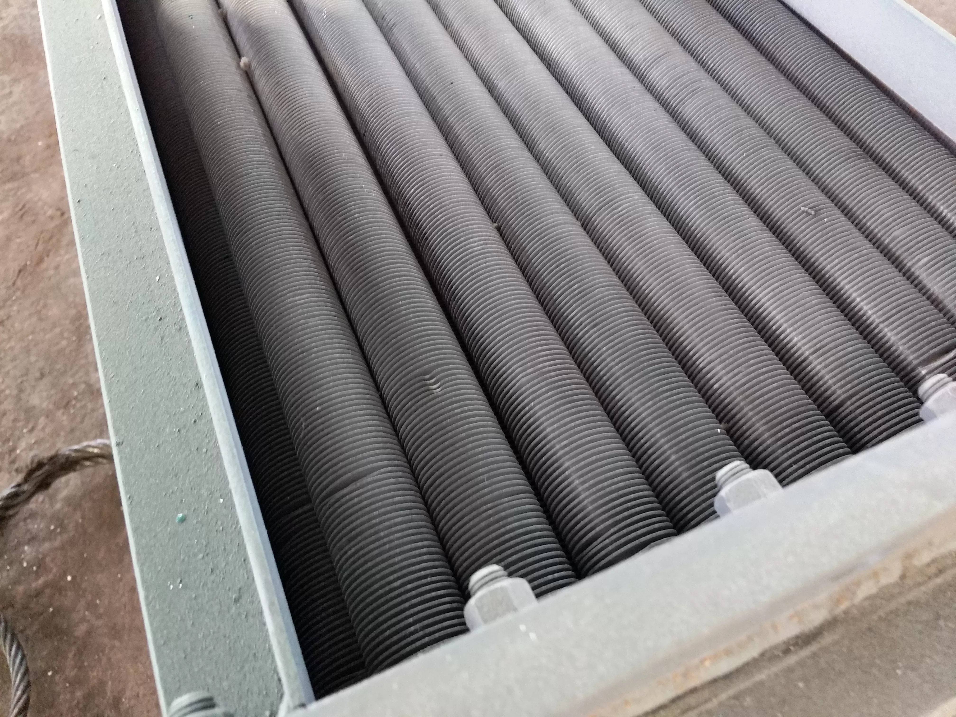
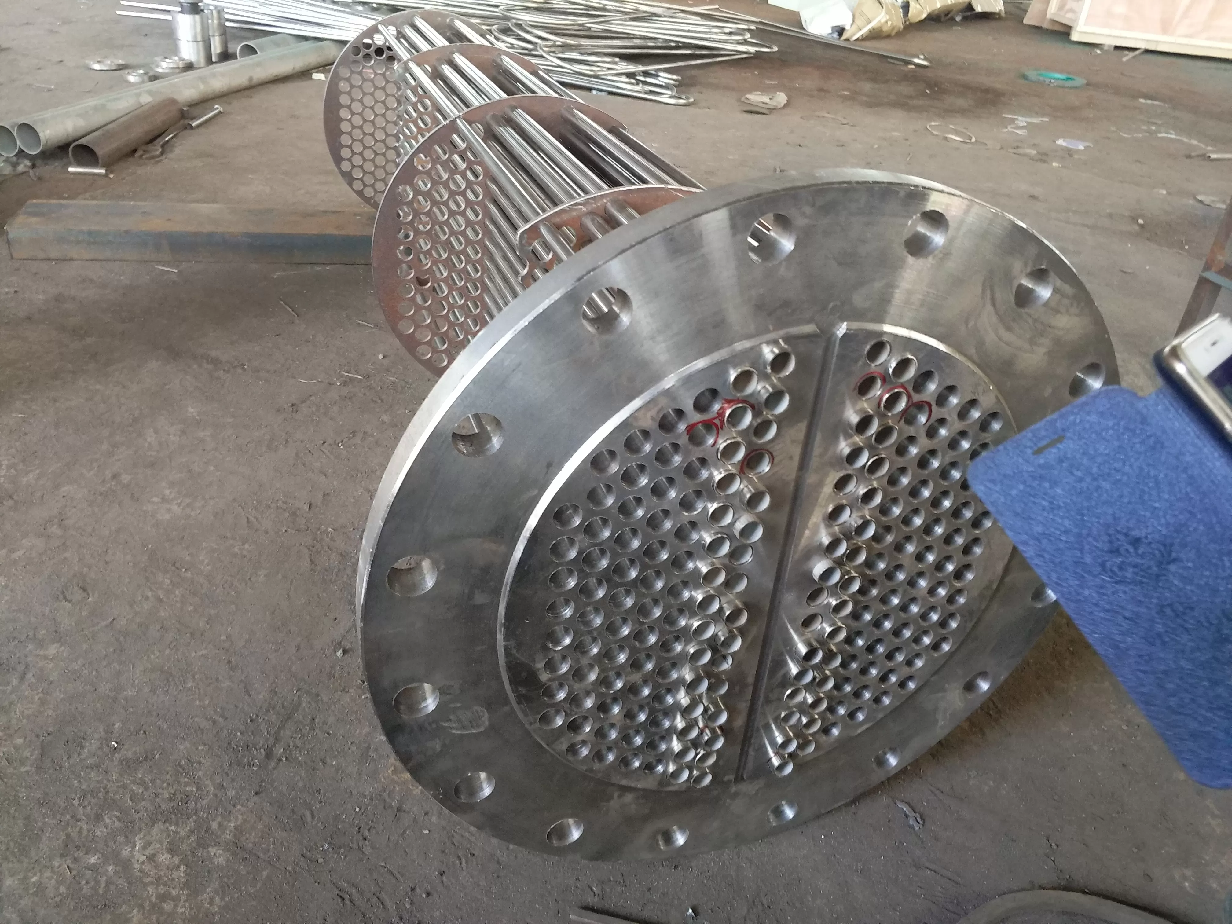
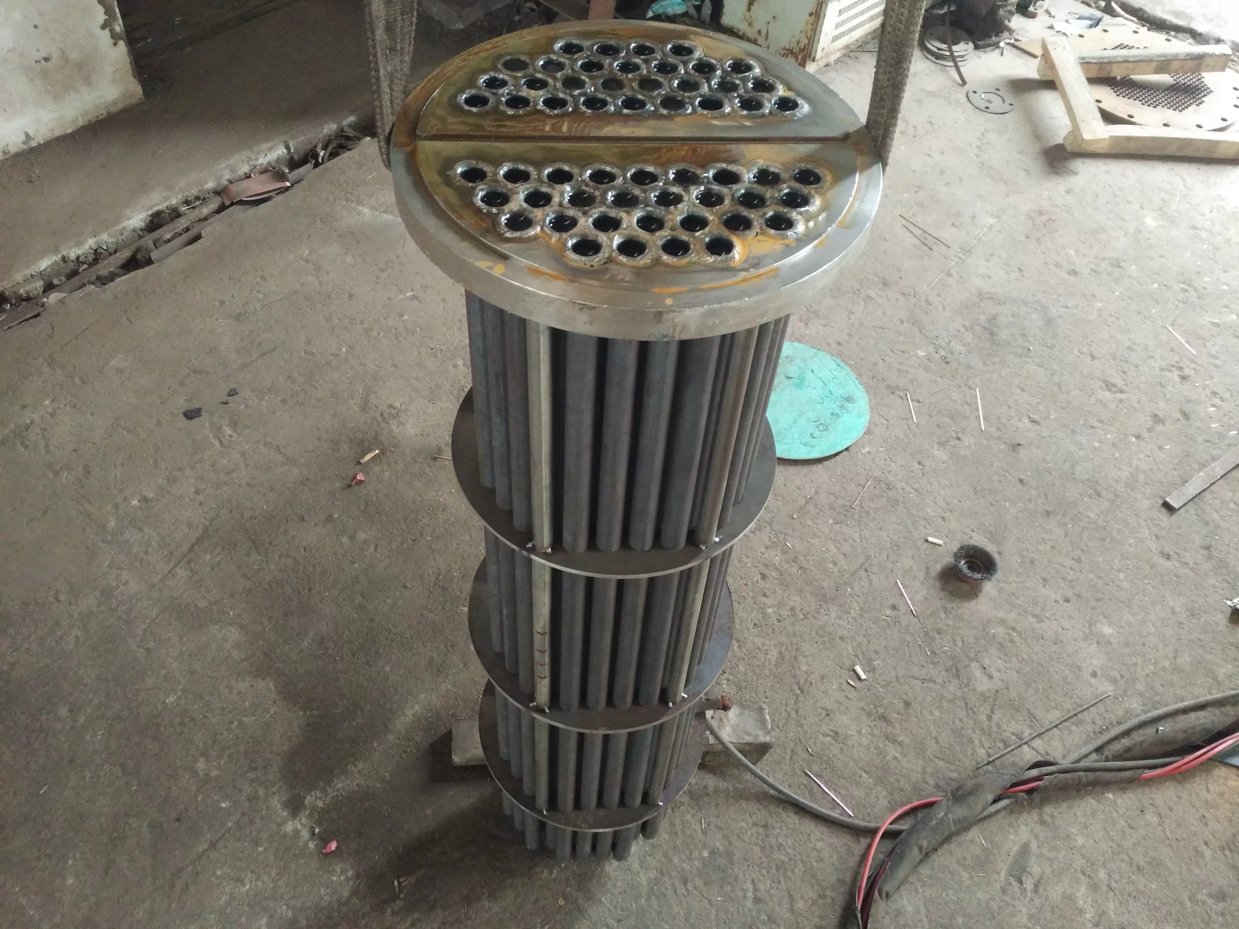
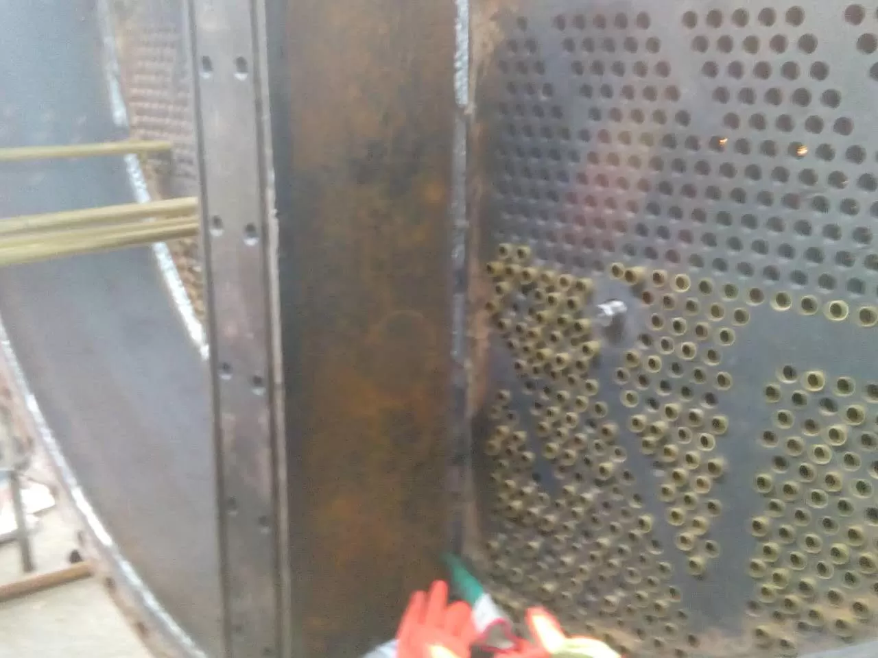
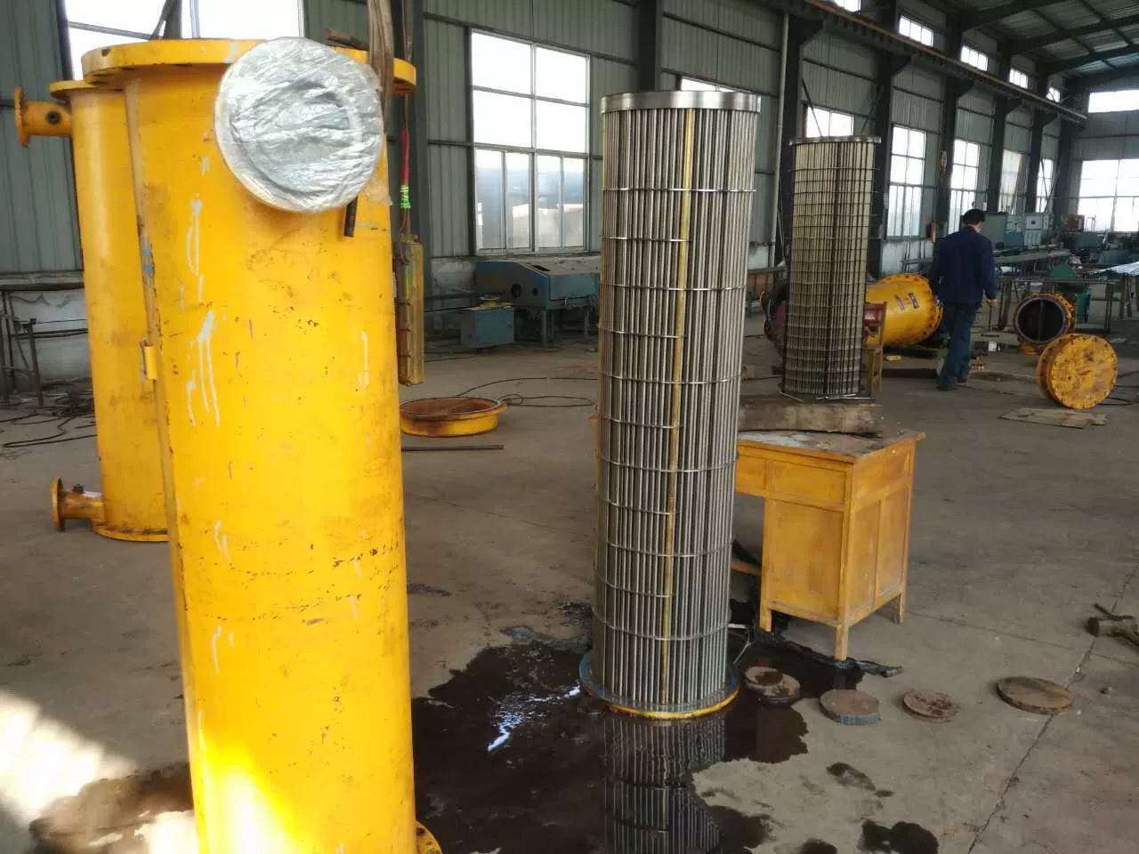
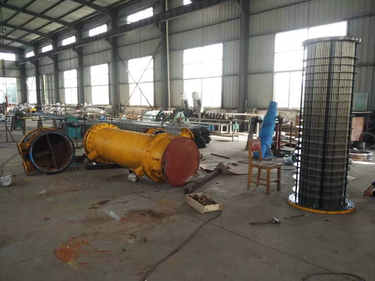
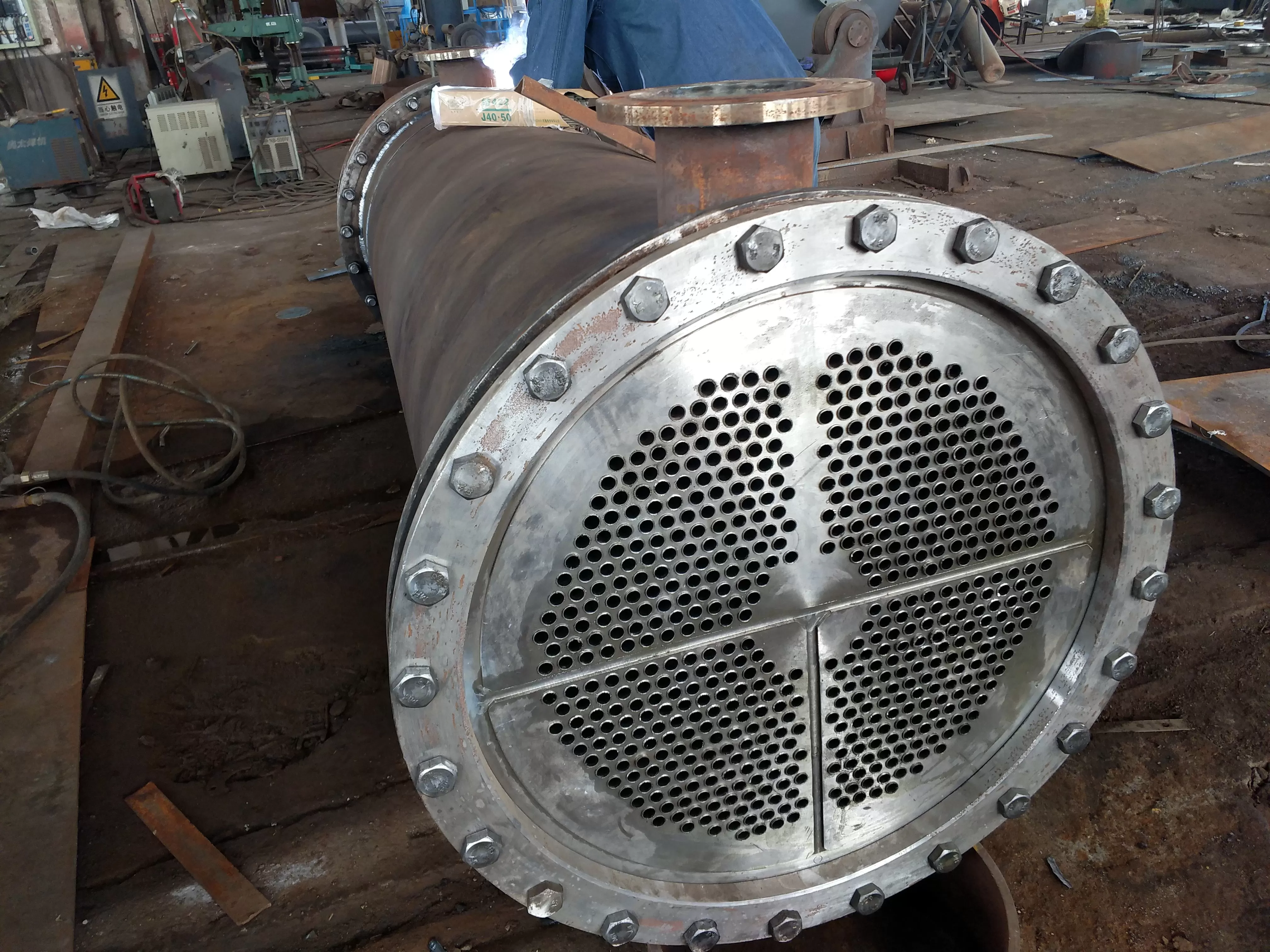
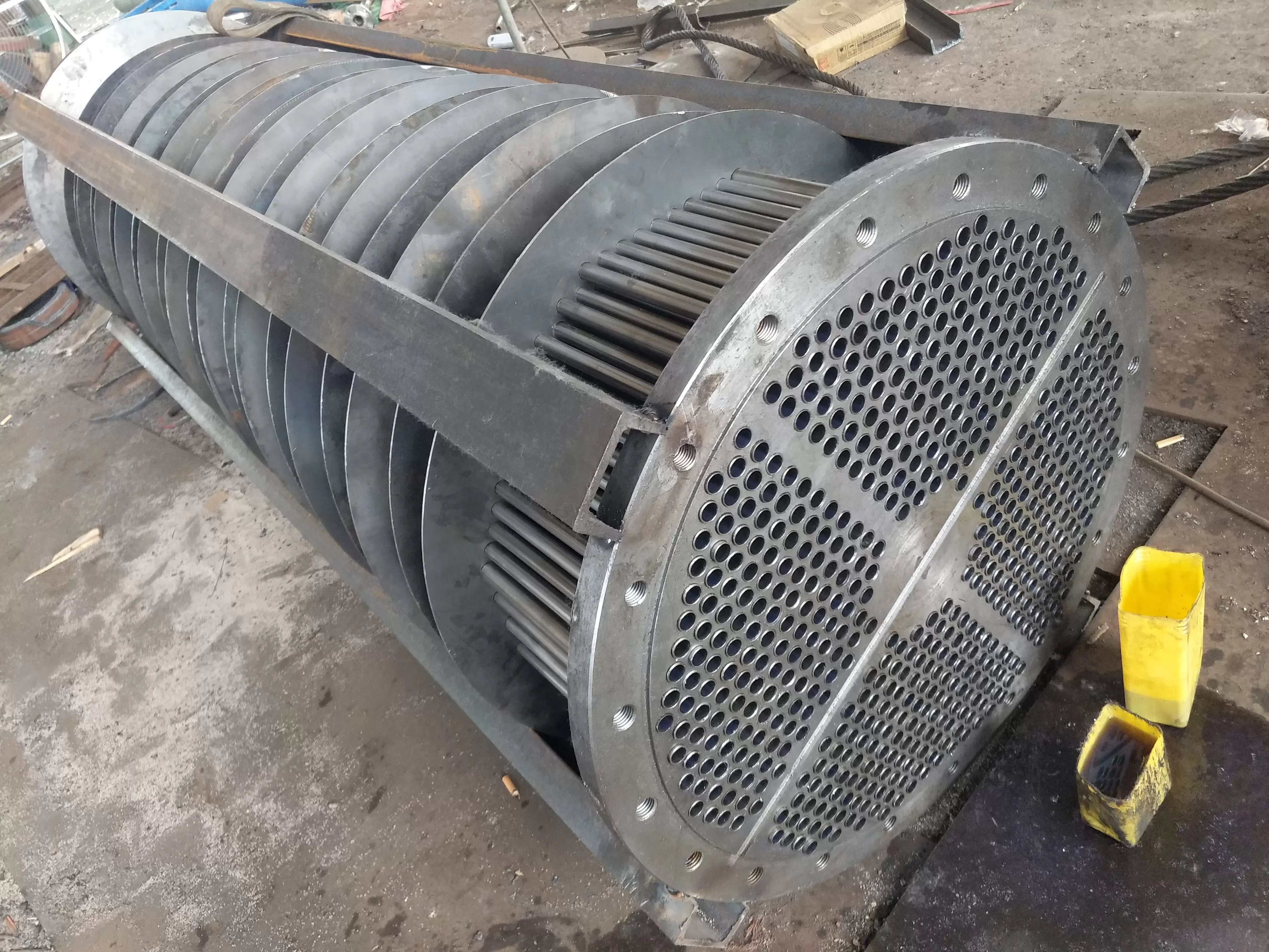
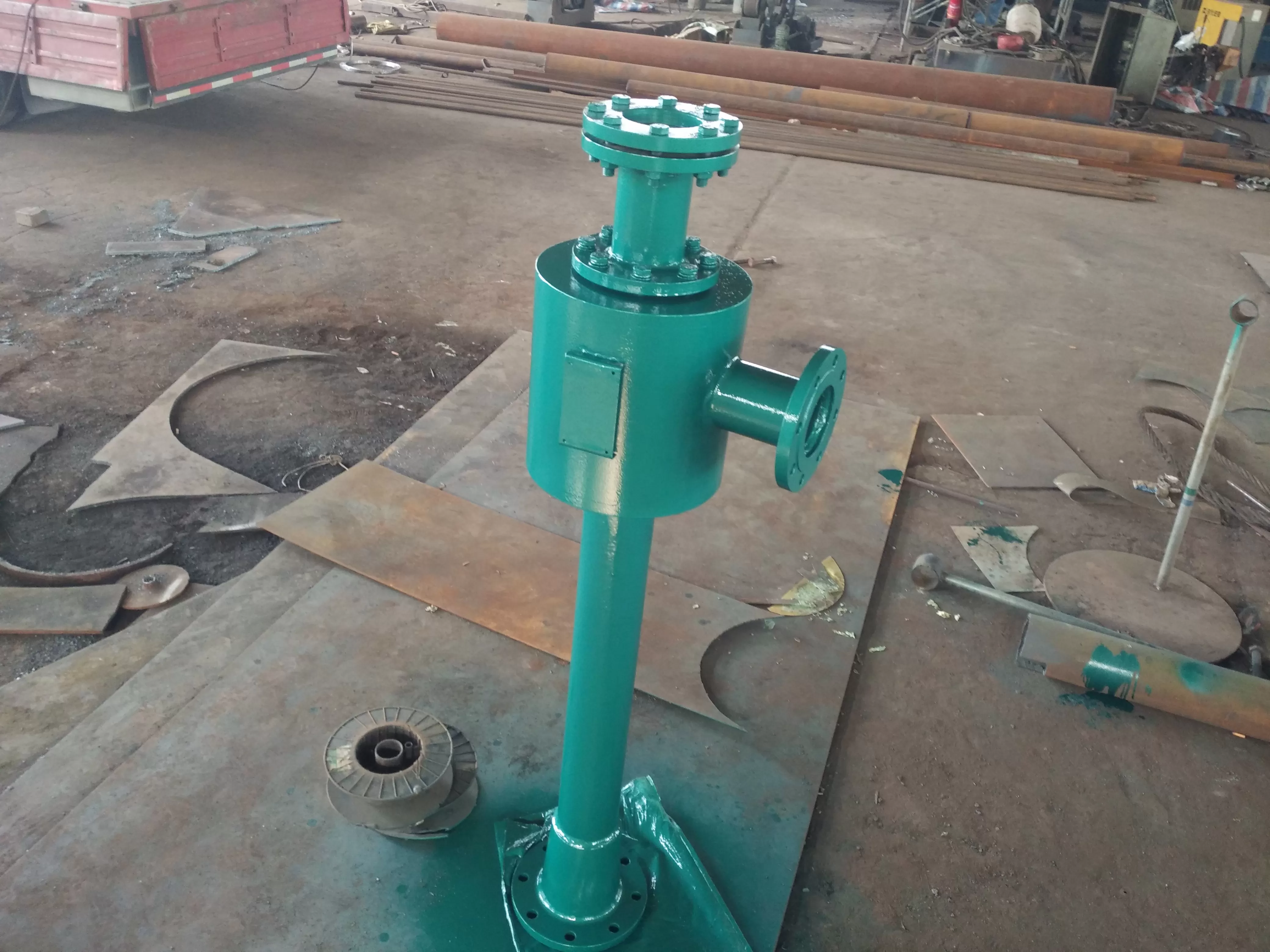
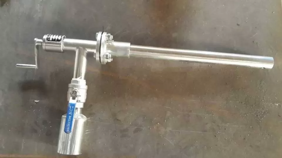
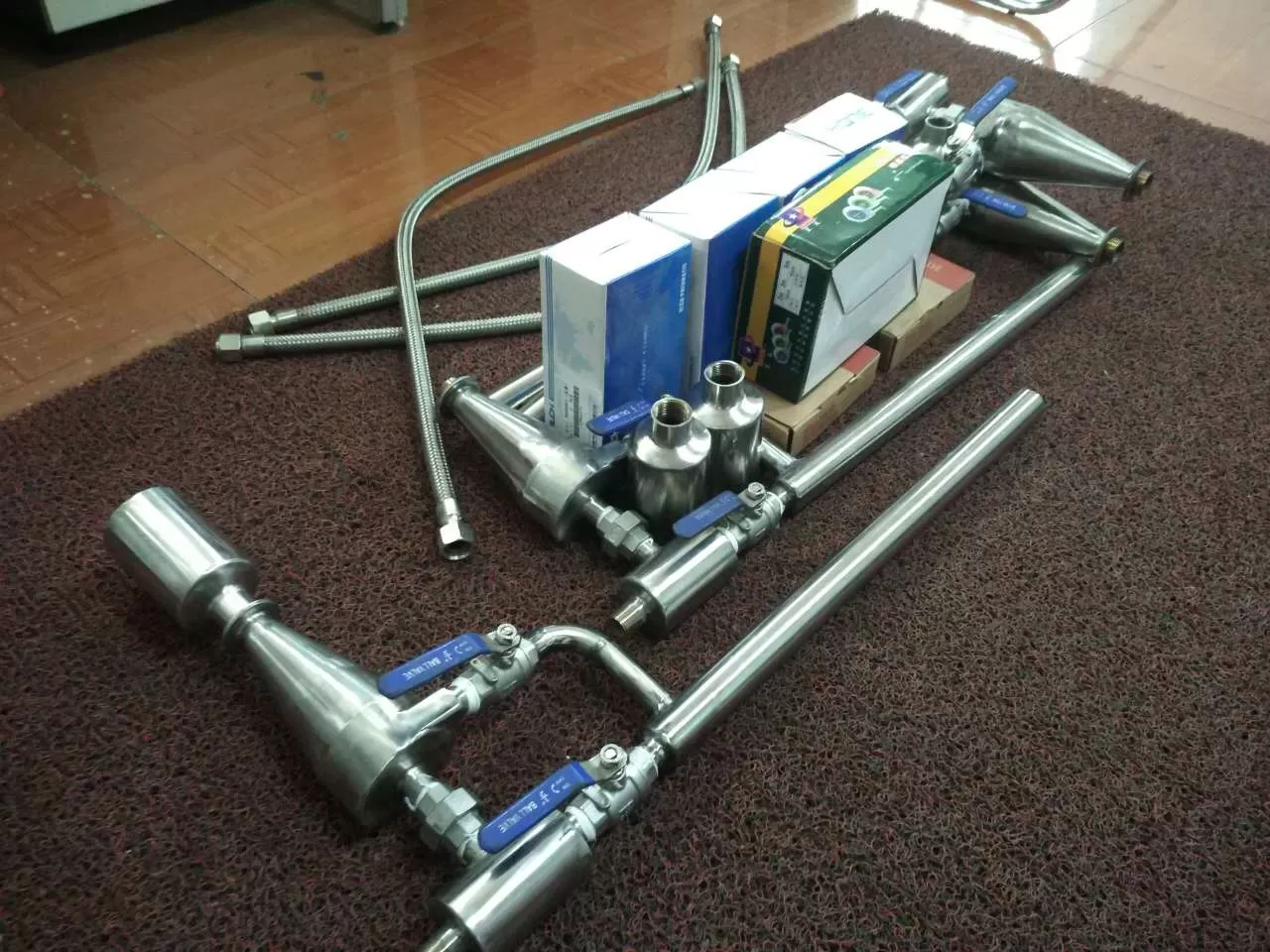
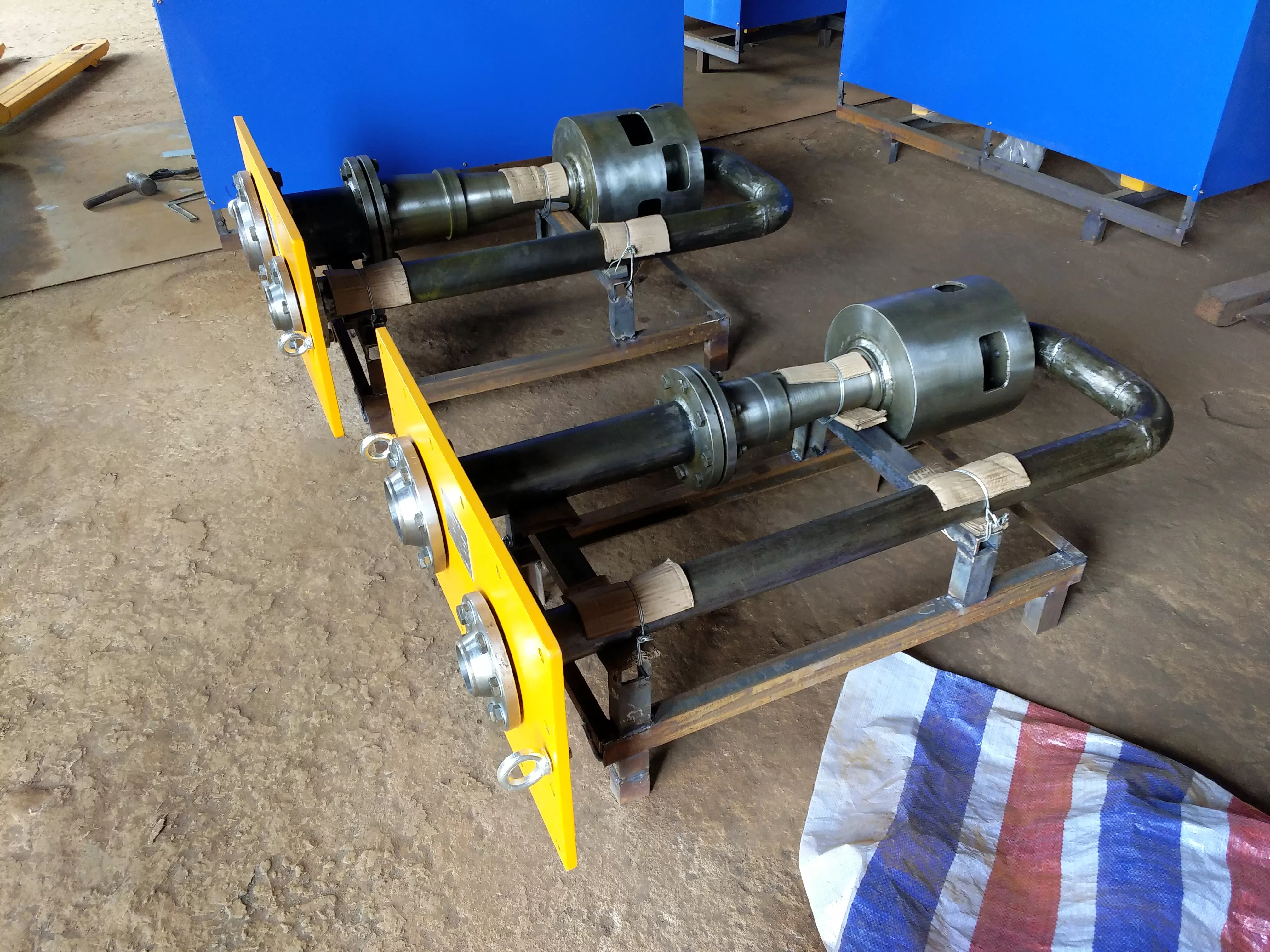
The hydrophobic expansion vessel adopts a fully welded structure, which is composed of components such as the shell, hydrophobic connecting pipe, spray pipe, buffer plate, waveform expansion joint, etc. The nozzle on the spray pipe adopts a nozzle to evenly spray the condensed water and achieve atomization. For the convenience of installation and layout of the power plant, the external design of the drainage expansion tank is a rectangular structure, arranged on the high-pressure condenser side and the low-pressure condenser side. Due to the limitations of the layout position, drainage capacity, and other auxiliary equipment of the power plant, as well as the drainage requirements, the size of the interface pipes of the two drainage flash tanks is not exactly the same. The drainage from various parts of the unit is discharged into the corresponding drainage main pipe through the drainage pipeline, and enters the drainage flash tank through the drainage connecting pipe on the drainage flash tank. There are a certain number of spray holes on each drainage pipe, which have a stepwise pressure reduction and energy dissipation effect on the water entering the expansion tank. Cooling water (condensate) is sprayed into the upper part of the expansion vessel through a nozzle on the spray pipe, causing the flash steam temperature inside the expansion vessel to rapidly decrease and condense, increasing the expansion capacity of the hydrophobic expansion vessel. Support rods and rib plates are also installed inside the shell to enhance the rigidity of the expander. Install buffer plates at the steam and water discharge outlets of the drainage flash tank to prevent the steam and condensate inside the flash tank from directly impacting the components inside the condenser and affecting the normal operation of the condenser. There is a maintenance manhole door on the hydrophobic expansion tank for maintenance, cleaning, and other purposes. Mechanical (free floating ball, lever floating ball, inverted bucket) steam traps are opened and closed using the principle of buoyancy. It can automatically distinguish between steam and water, and is used to collect and reuse water that requires continuous drainage, high flow rate, and discharge. The structure of the lever float trap and the inverted bucket trap is complex, while the structure of the free float trap is simple and non vapor, and is generally used for pipe or equipment drainage; Thermodynamic (disc type, pulse type) steam traps use the principles of aerodynamics to open and close valves by generating pressure drop from the turning of the vapor.
Used in areas with low flow rate, high differential pressure, and low requirements for continuity, with a simple structure and the presence of pulse leakage. Generally used for pipe drainage and secondary drainage expansion. Specific structure
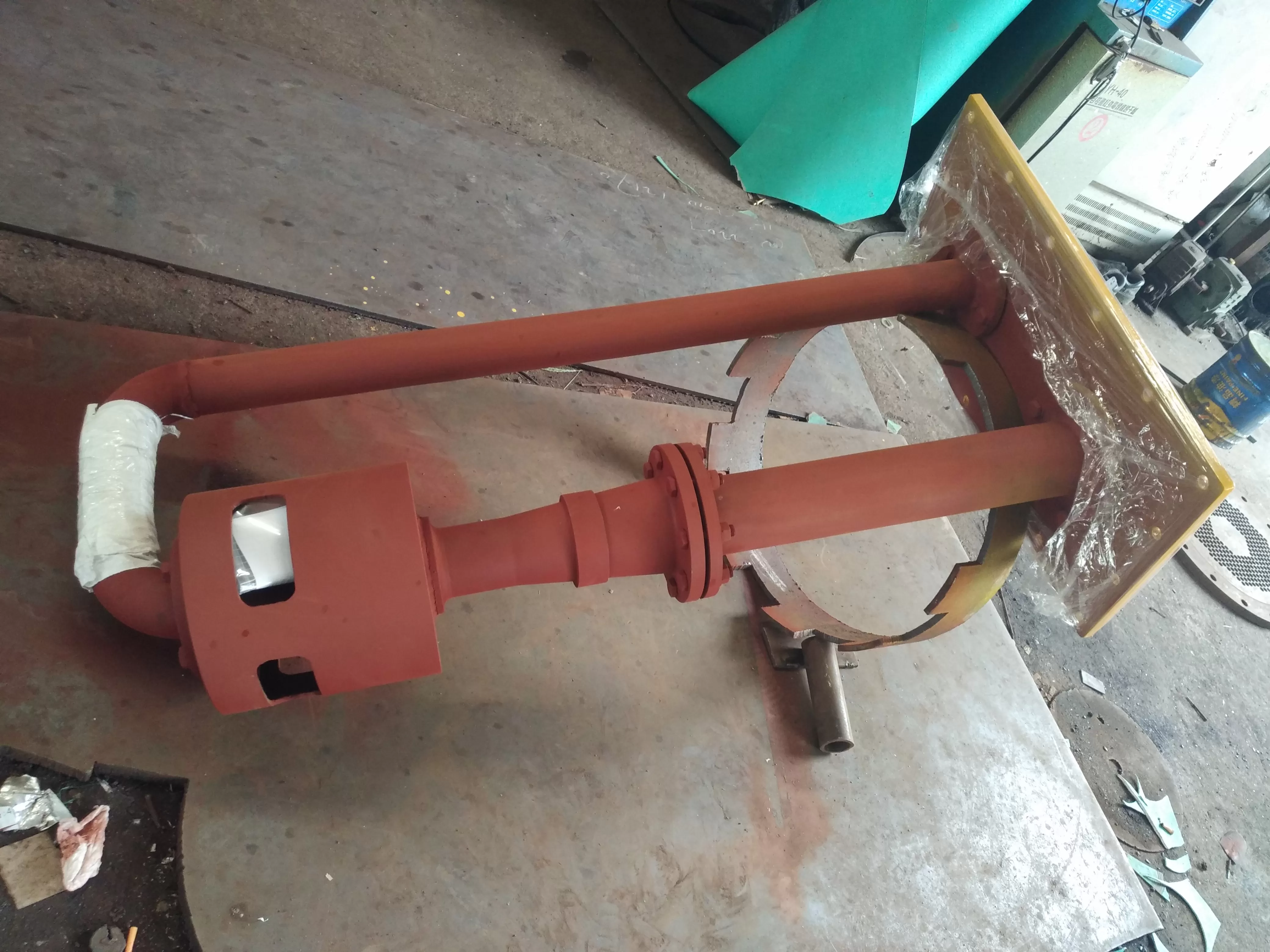
Composition, types, and representation methods of horizontal hydrophobic expansion vessels:
Steam turbine drainage expansion vessels can be divided into two types: vertical drainage expansion vessels and horizontal drainage expansion vessels
Composition of vertical hydrophobic expansion vessel -
1. Shell
2. Water inlet distributor
3. Effluent defoamer
4. Safety release device
5. Liquid level indicator
6. Composition of liquid regulating device. (The safety relief device and liquid level adjustment device are not within the scope of supply. If they are required to be matched at the same time, they must be specified in the contract.)
Hydrophobic expansion vessel, expansion vessel note: Various specifications of continuous discharge can be designed according to user needs, and technical parameters can be provided by the user.
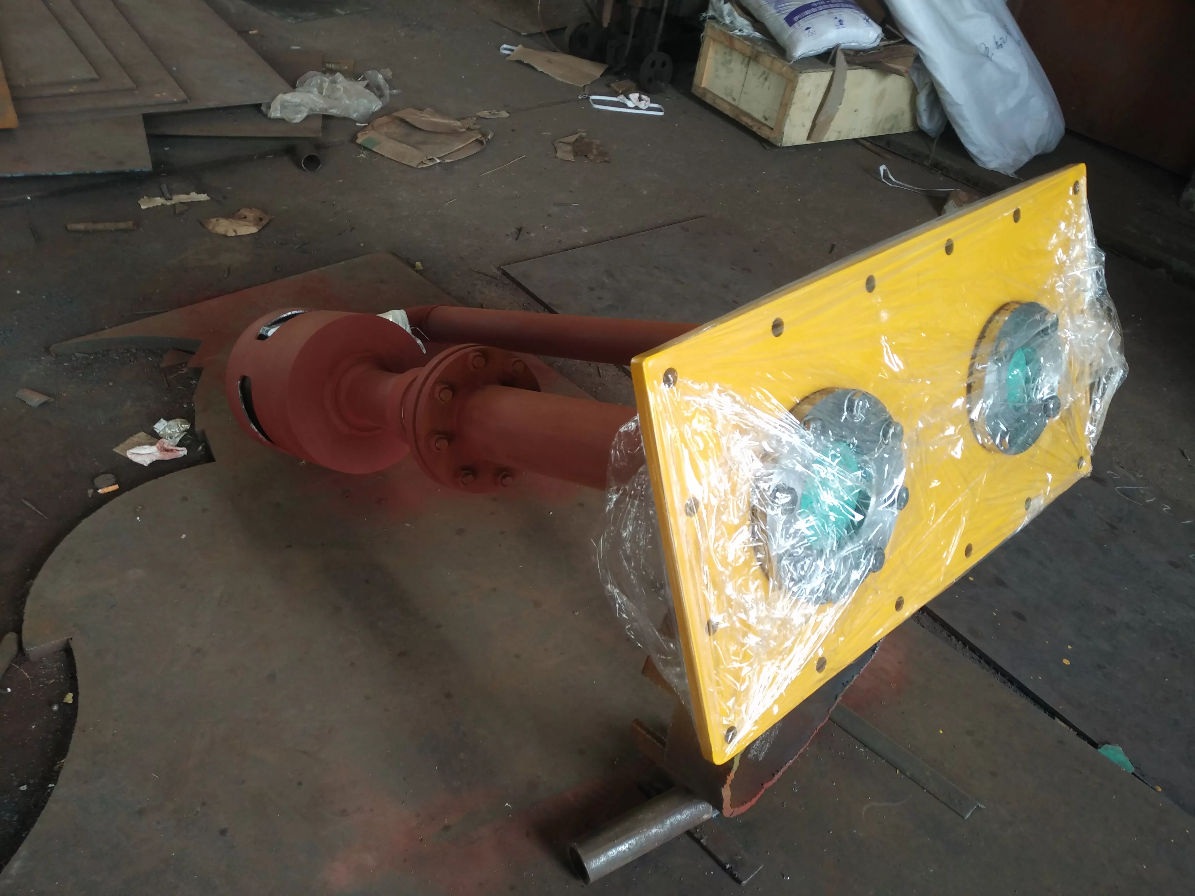
Composition of horizontal hydrophobic expansion vessel -
The composition of horizontal hydrophobic expansion vessels is similar to that of vertical hydrophobic expansion vessels.
A drainage flash tank is a device that expands and depressurizes the drainage flash tank of a pressure drainage pipeline, separates steam and drainage, and introduces steam into a heat exchanger or deaerator to fully utilize its heat energy. The drainage is then introduced into a drainage tank, which is regularly fed into the water supply system.
Hydrophobic expansion vessel, analysis of expansion vessel accidents:
On July 18, 2004, after the second impulse of Unit 2 entered the stage of complete trial operation, there were problems with loud noise and vibration when starting the drainage flash tank, especially after the unit was unloaded.
On the morning of July 19th, due to the power loss of the turbine monitoring system (TSI), the emergency trip protection system (ETS) of the unit turbine tripped, causing the unit load to drop from 270MW to 0. After shutdown, there was an abnormal situation where the pressure gauge pipe of the start-up drainage flash tank was washed off and flew out. Subsequently, on the afternoon of July 19th, July 31st, August 6th, and August 9th, four consecutive high load trips occurred, causing severe abnormal conditions in the start-up of the drainage flash tank. Metal fragments flew out of the exhaust pipe of the start-up drainage flash tank.
On site inspection found that the lower ring used to fix the expansion tube in the drainage expansion vessel and internal components of the expansion vessel had fallen off, the upper ring had deformed, and the lower drainage outlet was sealed by broken iron blocks. The internal structure had been severely damaged. From this, it can be concluded that the damage to the metal components inside the hydrophobic expansion vessel is caused by the direct entry of high-temperature and high-pressure steam into the hydrophobic expansion vessel, causing the pressure and temperature borne by the internal components of the hydrophobic expansion vessel to exceed the design pressure and temperature.
Hydrophobic expansion vessel, analysis of the causes of expansion vessel failure:
1. Analysis of drain flash tank, flash tank pipeline valve system:
Due to the use of fully open and fully closed pneumatic valves for the relevant drain valves of the unit, which cannot maintain an intermediate opening degree, during the hot and hot start-up process of the unit, although the steam temperature and pipe wall metal temperature are relatively high, only a small amount of drainage is required for the pipeline, the pneumatic drain valve can only be fully open, which may cause excessive high temperature and high pressure steam to enter the expansion vessel, which is not conducive to the safe operation of the expansion vessel. Therefore, it is necessary to improve the pipeline valve system to enable the unit to properly control the drainage amount under different operating conditions such as hot and hot start.
2. Analysis of hydrophobic expansion vessel, expansion vessel cooling water spray system:
Start the cooling spray water of the drainage expander - from industrial water. The water pressure of industrial water main pipe is about 0.4MPa. Trial operation - found that the pressure of the cooling water spray for starting the drainage expander was too low and the water volume was too small. In order to ensure that the high-temperature and high-pressure steam entering the start-up drainage expander during the start-up of the unit can be fully cooled and desorbed, so that the expander is not warm or pressurized, measures should be taken to increase the desorbing water pressure and increase the amount of desorbing water, such as increasing the pipe diameter and using desorbing spray water with higher stable water pressure. At the same time, it is necessary to enhance the cooling effect of the cooling water spray inside the expansion vessel, so that the cooling water spray can reach the spraying state inside the expansion vessel. However, the original design of the equipment manufacturer did not adopt a door atomization measure.
3. Analysis of DCS control logic for pneumatic drain valves in drainage expansion vessels:
4. Start the drain flash tank and control the pneumatic drain valve of the flash tank
(1) When the unit load is less than 20% of the rated load, open drain valves 1, 2, 3, and 4 (see Figure 1); When the load exceeds 22% of the rated load, connect the drain valve.
(2) When the reheat hot pipeline starts the drain tank, the reheat cold pipeline starts the drain tank, and the extraction steam pipeline drain tank, if the water level in any drain tank is high or high, the corresponding drain valve will be opened- Close the valve 15 seconds after the liquid level is high.
5. Problems with the control logic of the hydrophobic expansion vessel:
(1) The action of starting the drain valve in the main steam pipeline of the drainage expansion vessel is not reasonable, as the control condition is only based on the unit load. Because during the process of unit load rejection and shutdown, the process of reducing the unit from high load to 0 is very short. At this time, the steam parameters are still very high, even close to the design pressure of 17.75 MPa and the design temperature of 540 ℃. In terms of drainage, the main steam pipeline does not need to be drained at this time. However, according to the control logic, the load is less than 20% of the rated load at this time, so the drain valve is in a fully open state, and a large amount of high-temperature and high-pressure steam directly enters the startup drain flash tank, causing the flash tank to be overloaded, temperature and pressure tight, until internal components are damaged. In addition, during the hot start process where the unit starts up again shortly after being shut down due to load rejection, the temperature of the main steam pipeline and main steam is still very high. At this time, the control basis for starting the drain valve should not be solely based on the load. Therefore, in addition to the unit load, steam temperature, pipe wall temperature, or temperature change rate should also be introduced as the control basis for the operation of the drain valve.
(2) The analysis of the unit trip process shows that "the unit load is less than 20% of the rated load" is not a necessary drainage condition during the unit trip process. Therefore, "the unit load is less than 20% of the rated load" should only be a condition for opening the drain valve in the non tripping state of the unit.
(3) The control logic of the drainage flash tank requires that the unit load be less than 20% of the rated load, and the drain valve that enters the startup drainage flash tank should be opened in conjunction, without considering the bearing capacity of the startup drainage flash tank under this working condition- On the basis of ensuring the reliable and safe drainage of the steam turbine body, the load value of the initial drainage should be appropriately reduced after calculation and analysis, in order to maintain the drainage effect at low load while also considering the bearing capacity of the start-up drainage expander.
Hydrophobic expansion vessel - chemical economy - chemical scheme:
1. Improvement of hydrophobic expansion vessel, expansion vessel pipeline and valve system:
28 pneumatic drain valves have been installed for 1, 2, 3, and 4, respectively × The bypass pipeline of 3.5 and the manual and secondary valves of the bypass are shown in Figure l. In this way, the amount of drainage entering the start-up drainage flash tank can be controlled according to the operating conditions of the unit. If necessary, the bypass valve and secondary valve of the drainage valve can be opened appropriately for drainage, which can not only maintain the drainage effect but also prevent damage to the temperature and pressure of the start-up drainage flash tank.
2. Improvement of hydrophobic expansion vessel and cooling water spray device for expansion vessel:
Increase the diameter of the cooling water spray pipe for starting the drainage expander, from the original? forty-five × Change 2.5 to? fifty-seven × 3. To increase the cooling water volume. Change the temperature reducing spray water from industrial water to pressure high, water stable condensate water, and the operating condensate water main pipe pressure can reach 3.0 MPa. In order to enhance the cooling effect of the cooling water spray in the expansion container, we will also? fifty-seven × The cooling water spray pipeline of 3 extends into the interior of the start-up drainage flash tank. The extended part adopts the No. 20 boiler with sufficient strength
| 疏水扩容器型号 | 几何容积 m 3 | 设计压力 MPa | -高工作压力 MPa | 设备-量Kg | 设计温度 ℃ |
| SK0.5 | 0.5 | 0.2 | 0.2 | 340 | 150 |
| SK0.75 | 0.75 | 0.2 | 0.2 | 640 | 150 |
| SK0.75-II | 0.75 | 0.35 | 0.35 | 506 | 152 |
| SK1.0 | 1.0 | 0.2 | 0.2 | 715 | 150 |
| SK1.5 | 1.5 | 0.25 | 0.25 | 612 | 350 |
| SK1.5B | 1.5 | 1.2 | 1.2 | 1100 | 170 |
| SK2.0 | 2.0 | 0.2 | 0.2 | 820 | 150
|